Method, kit and target for multimode 3D imaging systems

a 3d imaging and multi-mode technology, applied in the direction of instruments, measurement devices, surveying and navigation, etc., can solve the problems of incompatibility with flat 2d contrast targets, and achieve the effect of greatly facilitating the alignment of images and object spaces

Active Publication Date: 2020-02-04
NAT RES COUNCIL OF CANADA
View PDF9 Cites 0 Cited by
  • Summary
  • Abstract
  • Description
  • Claims
  • Application Information

AI Technical Summary

Benefits of technology

[0017]Current 3D targets that can be used for large scale industrial dimensional metrology with contact retroreflector type devices (e.g. spherically mounted retroreflectors (SMR)) are incompatible with flat, 2D contrast targets. The former typically being nests and the latter are typically flat surfaces. One chief advantage of a multimodal target that combines these forms is that alignment of images and object spaces is greatly facilitated.
[0019]Advantageously, the mechanical reference features define the high contrast edges, so that measurement processes for 2D and 3D coordinate acquisition are similar, and use an overlapping set of points on the multimodal target (which reduces the number of reference features on the multimodal targets as well as the effort and cost required to align the multiple reference features during fabrication. The identification of an intersection of lines is a robust coordinate acquisition process. The edges of the multimodal target define both high contrast 2D targets at different viewing angles, and physical edges, so reliable and repeatable acquisition of spatial coordinates of a centre of the target is made possible using 3D (e.g. contact probing, photogrammetry, LiDAR, time of flight, and triangulation) measurement systems. A particular process and tool is provided for contact based acquisition, and a kit comprising the tool and target is provided.

Problems solved by technology

Current 3D targets that can be used for large scale industrial dimensional metrology with contact retroreflector type devices (e.g. spherically mounted retroreflectors (SMR)) are incompatible with flat, 2D contrast targets.

Method used


Image

  • Method, kit and target for multimode 3D imaging systems
  • Method, kit and target for multimode 3D imaging systems
  • Method, kit and target for multimode 3D imaging systems

Examples


examples

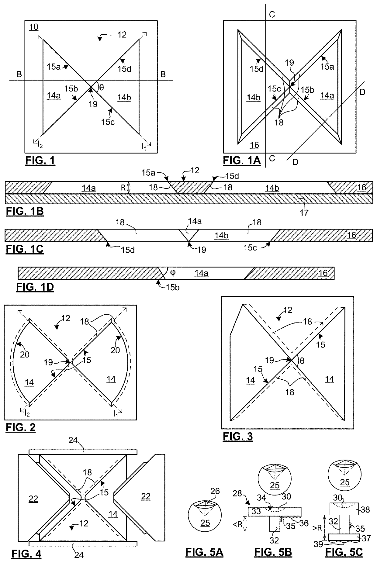
[0111]FIG. 7 is a photograph of an example of a multimodal target in accordance with the present invention. This example is made in the two piece design. The top piece is a square plate (10″ sides) of solid aluminum, 0.5″ thick. The square plate was machined by CNC machining. A φ=45° bevel was made from the back-side of the plate to form an undercut bevel from the front face of the target. A centre of the target, which crosses the both the lines I1,I2 at 45°, with I1,I2 meeting at 90°. A maximum width of the distal surfaces was about 6 inches and a 2″ frame is provided around the target face. Two boreholes are used for mounting and are located above and below the target face, substantially on centre. A black backing plate was adhered to the back of the machined top piece to form a high contrast target.

[0112]The photograph shows an image taken at an angle that is tilted in two directions. Despite the unusually large angle of imaging for most medium range (2-150 m) coordinate measurem...


PUM


Abstract

A technique for acquiring target's coordinates for industrial dimensional metrology involves a target that serves both as a 2D contrast target and a 3D contact target, and a metrology tool. The target has proximal and distal surfaces, at least some of which being primarily flat and facing a common normal direction. At least 3 mm separate the proximal and distal surfaces in the normal direction. Reflectivity factors of the distal and proximal surfaces differ by at least 20%. Risers connecting pairs of the proximal and distal surfaces are sufficiently undercut so that none of the risers are in view at nominal viewing angles. At least two reference edges are defined where risers meet proximal surfaces. The tool has meeting features for registration with the edges and primarily flat surfaces, in at least two registered positions, to permit a retroreflector of the tool to acquire coordinates the target centre.

Description

CROSS-REFERENCE TO RELATED APPLICATION[0001]This application claims the benefit of U.S. Provisional Patent Application No. 62 / 376,991 filed on Aug. 19, 2016, the contents of which are herein incorporated.FIELD OF THE INVENTION[0002]The present invention relates in general to targets for non-contact industrial dimensional metrology, and in particular to targets and target systems, of which a variety of non-contact measurement systems can reliably acquire spatial coordinates.BACKGROUND OF THE INVENTION[0003]Measuring object positions in space is a routine, but important activity in industry, and is generally called industrial dimensional metrology. The present invention is directed to large scale industrial dimensional metrology, which concerns measurements over a volume of a few cubic meters to several 100 meters cubed. There is always a need for higher accuracy, higher resolution, acquisition of spatial coordinates with lower cost measurement systems and equipment, in less acquisiti...

Claims


Application Information

Patent Timeline
Patent Type & Authority Patents(United States)
IPC IPC(8): G01B11/00G01C15/06G01C11/00G01B11/03
CPCG01B11/00G01B11/002G01C15/06G01B11/03G01C11/00
Inventor COURNOYER, LUCPICARD, MICHEL
Owner NAT RES COUNCIL OF CANADA
Why Eureka
Try Eureka