
Vehicle lighting fitting and method for manufacturing vehicle lighting fitting

a technology for vehicle lighting and manufacturing methods, applied in lighting and heating apparatus, applications, instruments, etc., can solve problems such as frictional sound and exert an influence on visual appearance, and achieve the effect of preventing or reducing friction

Active Publication Date: 2011-12-29
STANLEY ELECTRIC CO LTD
View PDF2 Cites 7 Cited by
  • Summary
  • Abstract
  • Description
  • Claims
  • Application Information

AI Technical Summary

Benefits of technology

[0007]The presently disclosed subject matter is made in view of the above and other circumstances, and is directed to a vehicle lighting fitting which can prevent or reduce problems due to friction which may occur between a housing and a lens, and a decorative member. Moreover, the vehicle lighting fitting can avoid frictional damage to the lens which in turn might exert an influence on visual appearance, and can also avoid or prevent a frictional sound from occurring due to the above-noted friction. A method for manufacturing such a vehicle lighting fitting is also disclosed.
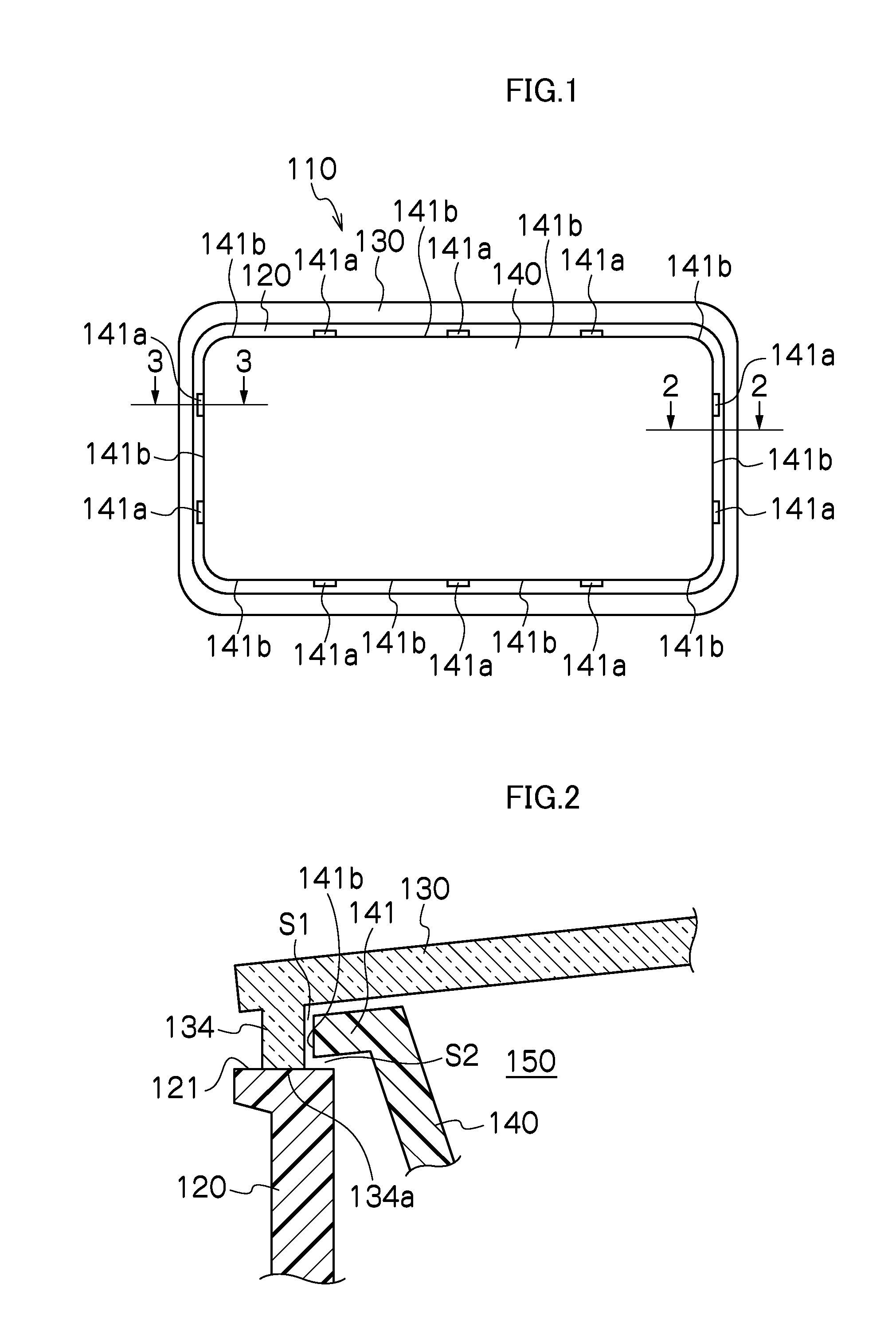
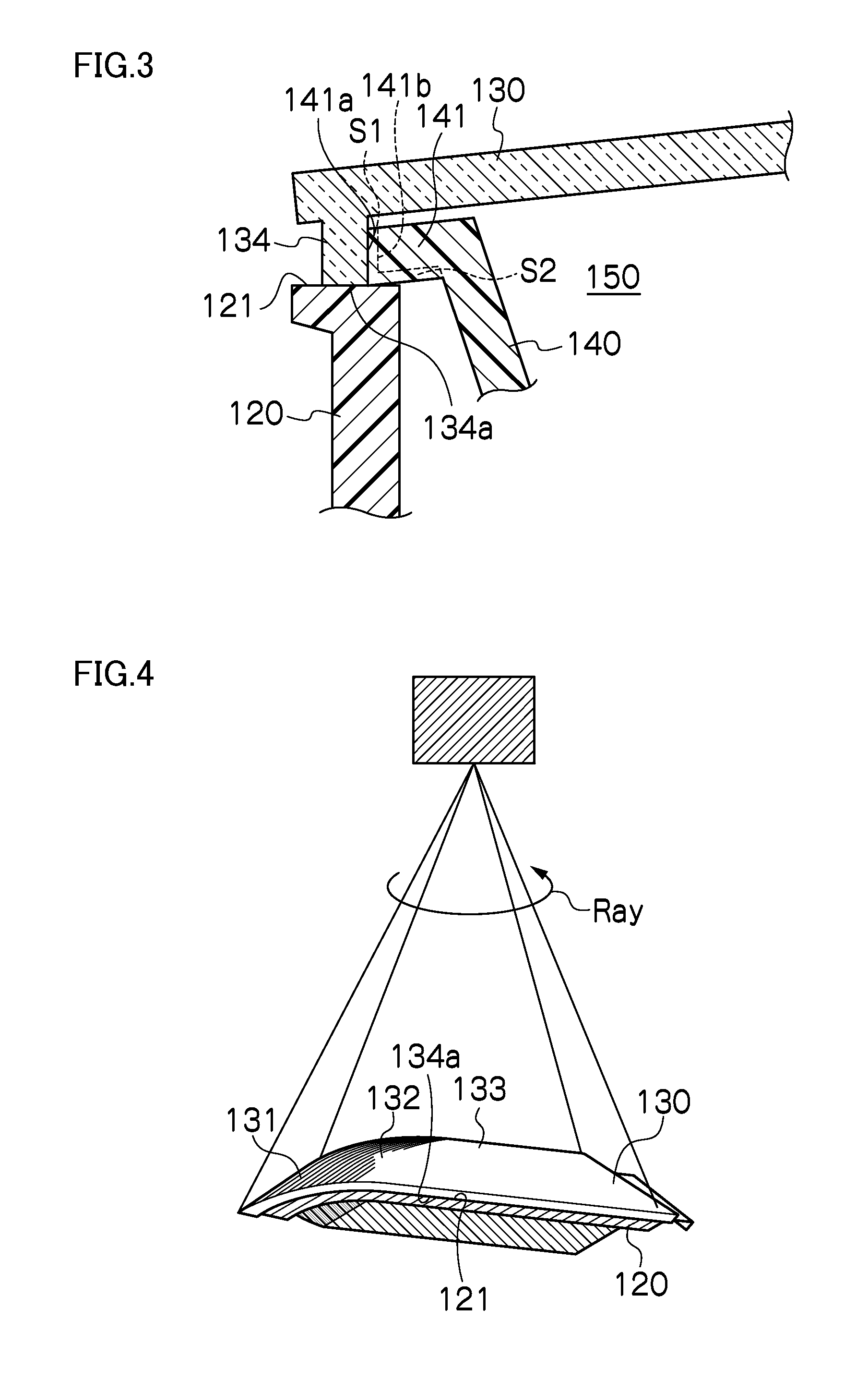
[0033]According to the above aspect of the presently disclosed subject matter, a vehicle lighting fitting can prevent or reduce friction which occurs between the housing and the lens, and the decorative member. The spots other than the laser-welded spots of the outer peripheral portion of the resin decorative member and a plurality of joint portions are not in close contact with one another (that is, the vehicle lighting fitting can prevent or reduce the problems that, due to friction, the lens is damaged to an extent that exerts an influence on the visual appearance, and in which a friction sound may occur).

Problems solved by technology

Therefore, there is a fear that friction is produced in the close contact portions by the influence of vibrations or the like at the time of traveling of the vehicle, resulting in problems in which the lens 420 is damaged and exerts an influence on visual appearance, and / or a frictional sound occurs.

Method used


Image

  • Vehicle lighting fitting and method for manufacturing vehicle lighting fitting
  • Vehicle lighting fitting and method for manufacturing vehicle lighting fitting
  • Vehicle lighting fitting and method for manufacturing vehicle lighting fitting

Examples


first embodiment

[0065]Hereinafter, a vehicle lighting fitting 110 according to the presently disclosed subject matter will be described with reference to the drawings.

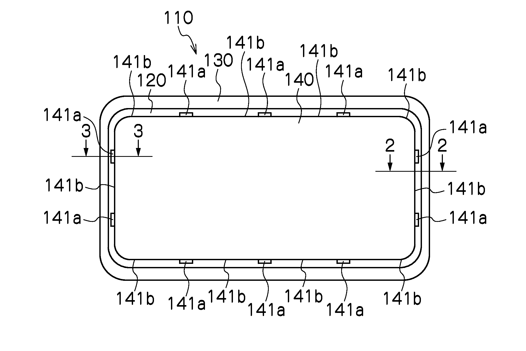
[0066]The vehicle lighting fitting 110 of the present embodiment is applied to, for example, vehicle lighting fittings such as rear combination lamps or the like which are respectively disposed at both left and right sides of a vehicle rear portion. The vehicle lighting fitting 110 includes a housing 120, a lens 130 and an extension 140, as illustrated in FIGS. 1 to 3. Of course, the disclosed subject matter can be incorporated into other types of lamps and fixtures, including headlights, turning lights, street lamps, decorative fixtures, and room lighting.

[0067]The housing 120 can be a thermoplastic resin having an absorption property with respect to a laser light (i.e., the thermoplastic resin can absorb at least a part of laser light so as to perform laser-welding). As illustrated in FIGS. 2 to 4, the housing 120 includes an openin...

second embodiment

[0086]Next, a vehicle lighting fitting 210 according to the presently disclosed subject matter will be described with reference to the drawings.

[0087]The vehicle lighting fitting 210 of the present embodiment is applied to, for example, vehicle lighting fittings such as rear combination lamps or the like which are respectively disposed at both left and right sides of a vehicle rear portion. The vehicle lighting fitting 210 can include a housing 220, a lens 230 and an extension 240, as illustrated in FIGS. 10 to 12. Of course, the disclosed subject matter can be incorporated into other types of lamps and fixtures, including headlights, turning lights, street lamps, decorative fixtures, and room lighting.

[0088]The housing 220 is a thermoplastic resin housing having an absorption property with respect to a laser light. As illustrated in FIG. 11B, the housing 220 includes an opening end portion 221. On the opening end portion 221 of the housing 220, a plurality of recessed portions 221a...

third embodiment

[0114]Next, a vehicle lighting fitting 310 according to the presently disclosed subject matter will be described with reference to the drawings.

[0115]The vehicle lighting fitting 310 of the present embodiment is applied to vehicle lighting fittings such as rear combination lamps or the like which are respectively disposed at both left and right sides of a vehicle rear portion, for example. The vehicle lighting fitting 310 can include a housing 320, a lens 330 and an extension 340, as illustrated in FIGS. 17 to 20. Of course, the disclosed subject matter can be incorporated into other types of lamps and fixtures, including headlights, turning lights, street lamps, decorative fixtures, and room lighting.

[0116]The housing 320 can be a thermoplastic resin housing having an absorption property to a laser light. As illustrated in FIGS. 18 and 20, the housing 320 includes an opening end portion 321. On an inside of the opening end portion 321 of the housing 320, a plurality of joint portio...


PUM

PropertyMeasurementUnit
groove widthaaaaaaaaaa
perimetersaaaaaaaaaa
heightaaaaaaaaaa

Abstract

A vehicle lighting fitting can include a housing including an opening end portion, a lens, an outer peripheral portion of which is laser-welded to the opening end portion to define a lighting chamber, and a decorative member disposed in the lighting chamber. The resin decorative member can include an outer peripheral portion on which a joint portion and a non-joint portion are alternately formed along a perimeter thereof, wherein the joint portion of the decorative member and the opening end portion of the housing are laser-welded in a state in which clearances are maintained between the non-joint portion of the decorative member and the housing, and between the lens and the housing.

Description

[0001]This application claims the priority benefit under 35 U.S.C. §119 of Japanese Patent Application Nos. 2010-143811 and 2010-143812 which were both filed on Jun. 24, 2010 and Japanese Patent Application No. 2010-165186 which was filed on Jul. 22, 2010, and which are all hereby incorporated in their entirety by reference.BACKGROUND[0002]1. Field[0003]The presently disclosed subject matter relates to a vehicle lighting fitting and a manufacturing method of a vehicle lighting fitting. The disclosed subject matter particularly relates to a vehicle lighting fitting which can prevent or reduce problems such as, due to friction which occurs between a housing and lens, and a decorative member, the lens may be damaged and exerts an influence on visual appearance, and wherein a frictional sound may be caused.[0004]2. Description of the Related Art[0005]As illustrated in FIG. 29, there has been conventionally known a vehicle lighting fitting 400 which is constructed by laser-welding an ope...

Claims


Application Information

Patent Timeline
Patent Type & Authority Applications(United States)
IPC IPC(8): F21V5/00B32B37/06F21S8/10
CPCB29C66/116B29C66/542B29C66/1222B29C66/1224B29C66/12449B29C66/12463B29C66/12469B29C66/131B29C66/1312B29C66/232B29C66/301B29C66/3452B29C66/543B29L2031/747F21V17/101B29C66/1162B29C66/24244B29C65/1635B29C65/1654B29C66/112B29C66/114B29C66/1142F21S48/1208F21S48/1233F21S48/2206F21S48/33B29C65/1667B29L2031/30B29C66/8322B29C66/73921B29K2995/0027B29C65/7814F21S41/29F21S41/28F21S43/27F21S45/50B29C65/1661B60Q1/00
Inventor HOKODA, KAZUAKIZAITSU, YOSHIHIROUMEYAMA, TATSUYAAKABANE, TAKASHI
Owner STANLEY ELECTRIC CO LTD
Learn More