Tissue cutting systems and methods

a cutting system and tissue technology, applied in the field of tissue cutting systems and methods, can solve the problems of obstructing the desired blood flow of heart valve leaflets

Pending Publication Date: 2022-09-15
UNITED STATES OF AMERICA +1
View PDF0 Cites 0 Cited by
  • Summary
  • Abstract
  • Description
  • Claims
  • Application Information

AI Technical Summary

Benefits of technology

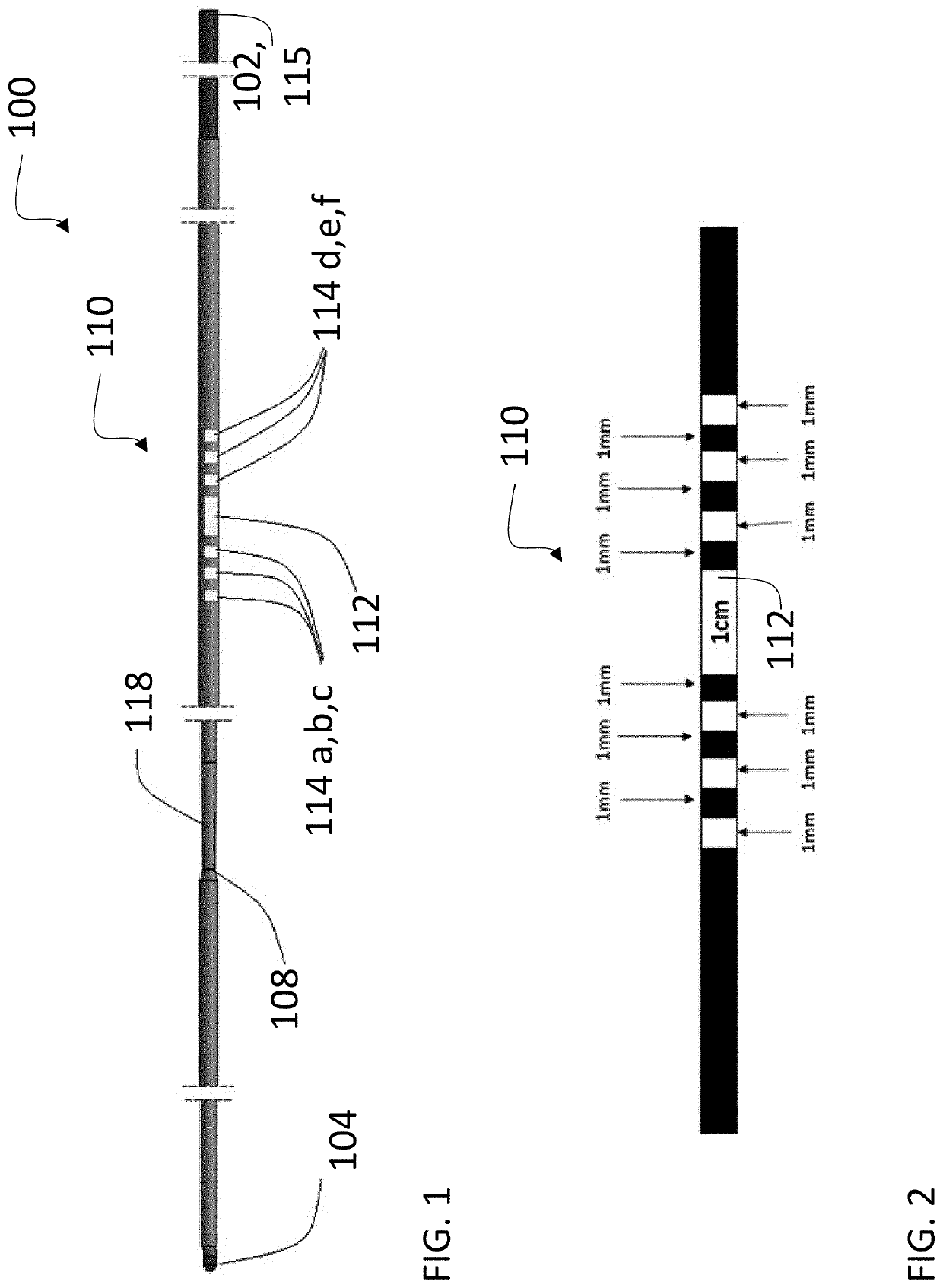
[0006]In some implementations, an irrigation catheter can also be used to inject a non-ionic liquid adjacent to the exposed portions of the cutter to displace blood and reduce with electrical dissipation. The disclosed cutters can be used in various methods disclosed herein to cut heart valve leaflets within the heart, including, for example, at the aortic valve, mitral valve, tricuspid valve, and pulmonary valve, as well as other types of tissue structures. Cutting valve leaflets can help prevent or reduce problems associated with the leaflets blocking desired blood flow, especially when a prosthetic heart valve is implanted within a native heart valve, or within another prosthetic heart valve.
[0020]In some implementations, the valve leaflet can be punctured at a position located radially inwardly from a valve annulus. This is sometimes needed to as to avoid the need for puncturing the valve leaflet too close to the valve annulus where calcified deposits may have accumulated. Once the leaflet has been so punctured by a guidewire as set forth herein, a catheter including an inflatable member, such as a balloon, or other expansible catheter can be introduced over the guidewire and introduced through the hole in the leaflet. The inflatable member can then be expanded to enlarge the opening in the leaflet at least partially along a radially outward direction toward the valve annulus.
[0021]The distal tip of each guiding catheter can be advanced under visualization to a location proximal to the kinked denuded region of the guidewire, and indicia on the guidewire can be used to maintain a predetermined spacing between the guiding catheters and the kinked denuded region of the guidewire to prevent damage to the guiding catheters.

Problems solved by technology

Heart valve leaflets can obstruct desired blood flow in some circumstances, such as when a leaflet is pushed into an open position by the implantation of a prosthetic heart valve within another.

Method used


Image

  • Tissue cutting systems and methods
  • Tissue cutting systems and methods
  • Tissue cutting systems and methods

Examples


Embodiment Construction

[0054]The present application presents advantages and improvements over systems described in U.S. patent application Ser. No. 16 / 954,710 (“the '710 application”), filed in the United States of America on Jun. 17, 2020. This patent application is incorporated by reference herein in its entirety for all purposes.

[0055]Applicant has come to appreciate that while the procedure set forth in the '710 application mentioned above is beneficial with respect to the mitral valve to prevent left ventricular outflow tract (LVOT) obstruction, the present disclosure provides specialized equipment that is far more useful as compared to the equipment to perform the procedure set forth in the '710 application. Moreover, the present disclosure adds the particular example of cutting leaflet(s) of the aortic valve so as to prevent obstruction of the coronary arteries. The disclosed embodiments make these types of procedures safer, faster, more consistent and predictable so as to make it a more practical...


PUM

PropertyMeasurementUnit
dielectric strengthaaaaaaaaaa
thicknessaaaaaaaaaa

Abstract

The disclosure provides various embodiments of systems to facilitate the cutting of luminal tissue structures percutaneously.

Description

CROSS-REFERENCE TO RELATED APPLICATION[0001]The present patent application claims the benefit of priority to International Patent Application No. PCT / US21 / 49952, filed Sep. 10, 2021, which in turn claims the benefit of priority to U.S. patent application Ser. No. 17 / 148,616, filed Jan. 14, 2021, U.S. patent application Ser. No. 17 / 148,170, filed Jan. 13, 2021, U.S. Patent Application No. 63 / 077,579, filed Sep. 12, 2020 and International Patent Application No. PCT / US2020 / 055160, filed Oct. 9, 2020. This patent application also claims the benefit of priority to U.S. patent application Ser. No. 17 / 148,170, filed Jan. 13, 2021, which in turn claims the benefit of priority to U.S. Patent Application No. 63 / 047,995, filed Jul. 3, 2020, U.S. Patent Application No. 63 / 077,579, filed Sep. 12, 2020 and International Patent Application No. PCT / US2020 / 055160, filed Oct. 9, 2020.FEDERALLY-SPONSORED RESEARCH AND DEVELOPMENT[0002]This invention was made with Government support under contract no. H...

Claims


Application Information

Patent Timeline
Patent Type & Authority Applications(United States)
IPC IPC(8): A61M25/09A61M25/01A61B90/00
CPCA61M25/09A61M25/0108A61B90/39A61M2025/09175A61M2025/09166A61B2090/3966A61M2025/09125A61B2090/061A61B18/1492A61B2018/144A61B2018/00136A61B2018/00083A61B2018/00369
Inventor RAFIEE, NASSERLEDERMAN, ROBERT J.BUSOLD, RANYHOUSE, MORGANKHAN, JAFFARROGERS, TOBYBRUCE, CHRISTOPHER G.
Owner UNITED STATES OF AMERICA
Why Eureka
Try Eureka