
Liquid ejection head and liquid ejection apparatus
a liquid ejection and apparatus technology, applied in electrical devices, piezoelectric/electrostrictive/magnetostrictive devices, printing, etc., can solve the problems of concentrated distortion, increased liquid ejection by piezoelectric element flexing, etc., to prevent or reduce problems, increase the amount of liquid to be ejected
- Summary
- Abstract
- Description
- Claims
- Application Information
AI Technical Summary
Benefits of technology
Problems solved by technology
Method used
Image

Examples
Embodiment Construction
1. General Configuration of Liquid Ejection Head
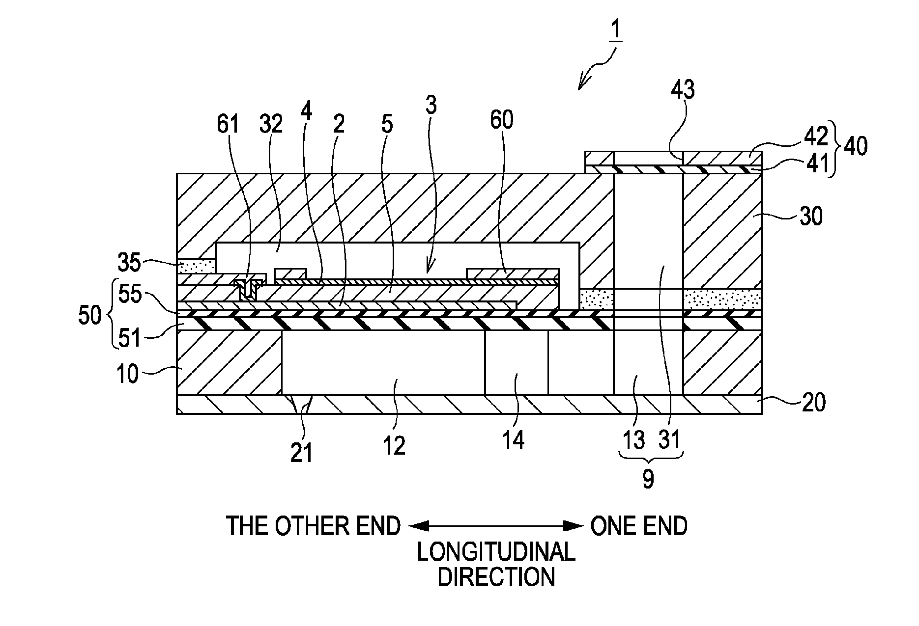
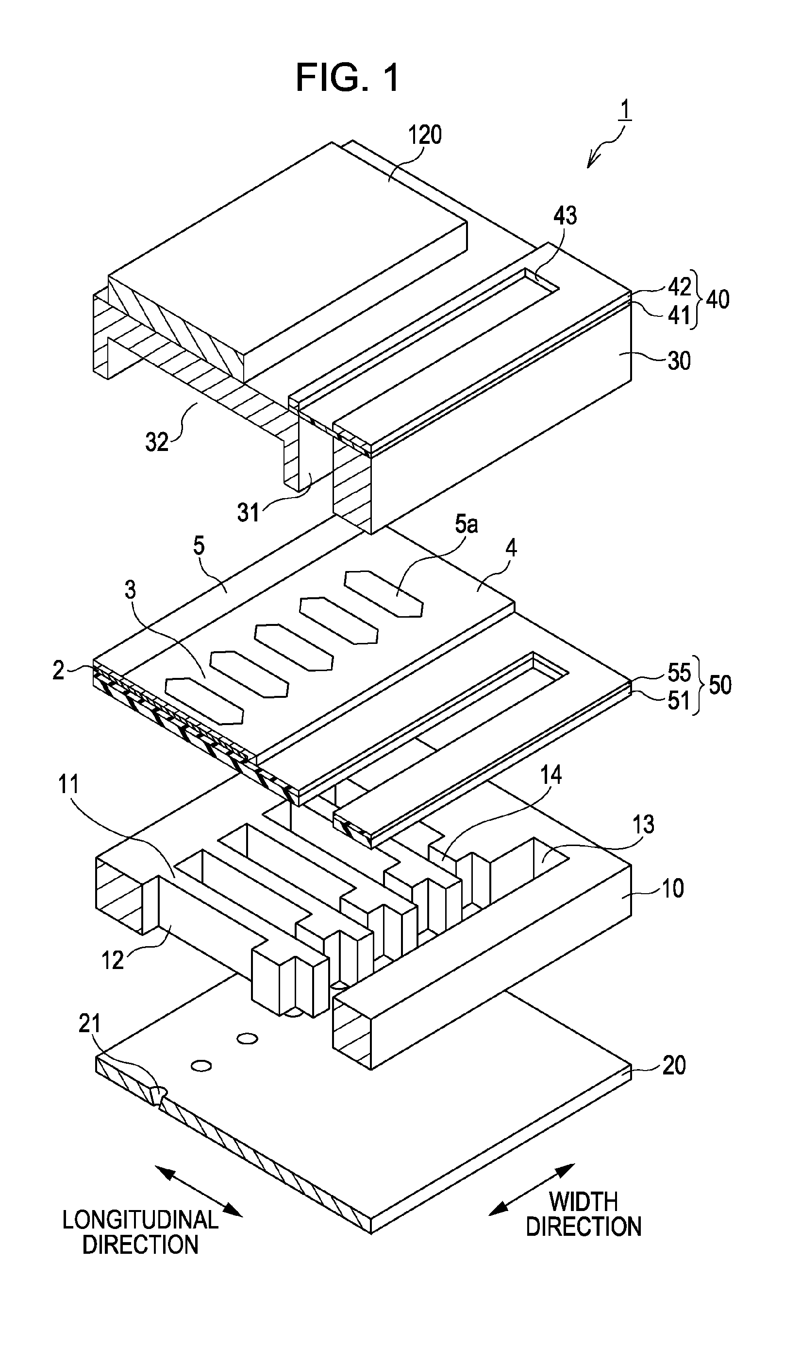
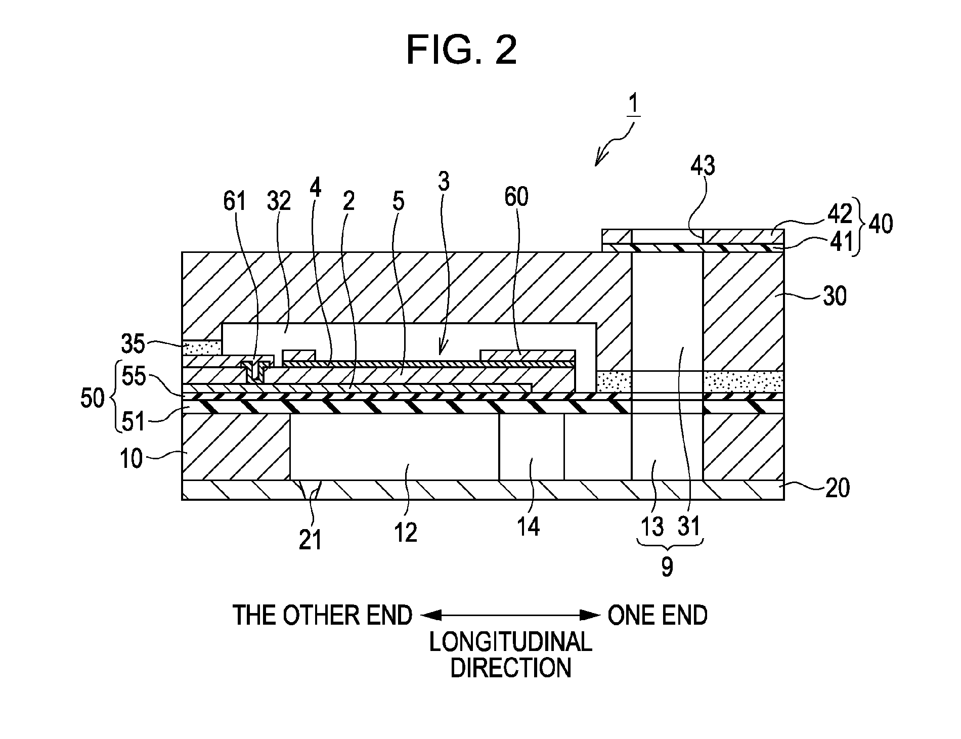
[0022]An embodiment of the invention will be described below with reference to the drawings. FIG. 1 is an exploded perspective view which schematically shows an ink jet recording head 1 (hereinafter, referred to as recording head 1) which is an example of liquid ejection head. FIG. 2 is a vertical sectional view of the recording head 1 in a plane parallel to the longitudinal direction of a pressure generating chambers 12 and passing through a lower electrode film 2 that corresponds to one of the pressure generating chambers 12. The recording head 1 includes a substrate (flow path forming substrate) 10. The substrate 10 is formed of, for example, a silicon single crystal substrate with a vibration plate 50 disposed on one side thereof. The vibration plate 50 includes, for example, an elastic film 51 formed of an oxide film that is in contact with the substrate 10, and an insulator film 55 formed of an oxide film made of a material diffe...
PUM
 Abstract
Description
Claims
Application Information