Pavement maintenance vehicle

A technology for car maintenance and car body, applied in roads, roads, road repair and other directions, can solve problems such as low cleaning efficiency, nozzle blockage, road damage, etc., to reduce workload and prevent nozzle blockage.

Inactive Publication Date: 2020-11-03
陈碧香
View PDF0 Cites 2 Cited by
  • Summary
  • Abstract
  • Description
  • Claims
  • Application Information

AI Technical Summary

Problems solved by technology

[0002] During the use of highways, due to the impact of rolling, impact, wear and weather changes on the road surface, it often causes defects and damage to the road surface. Road surface damage affects the vehicle's driving speed, load capacity, fuel consumption, mechanical wear, and driving comfort, as well as harmful effects on traffic safety and environmental protection. In order to prevent road surface damage and maintain a good technical condition of the road surface, the road surface will be maintained. During the road surface maintenance, as

Method used


Image

  • Pavement maintenance vehicle
  • Pavement maintenance vehicle
  • Pavement maintenance vehicle

Examples


Embodiment 1

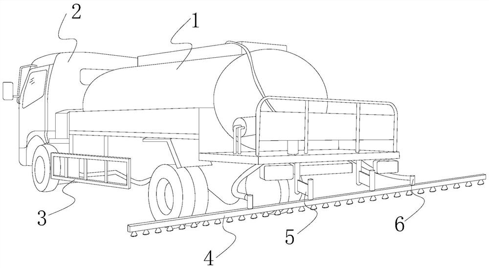
[0030] see Figure 1-6 , the present invention provides a technical solution of a road maintenance vehicle: its structure includes an asphalt spreader 1, a vehicle body 2, a side bracket 3, a spraying pipe 4, a connecting frame 5, and a delivery pipe 6. The two parts of the vehicle body 2 Side brackets 3 are provided on both sides, and an asphalt spreader 1 is arranged on the car body 2. The asphalt spreader 1 is connected to the spray pipe 4 through the delivery pipe 6, and the spray pipe 4 is connected to the spray pipe 4 through the connecting frame 5. Body 2.

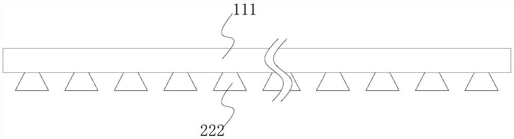
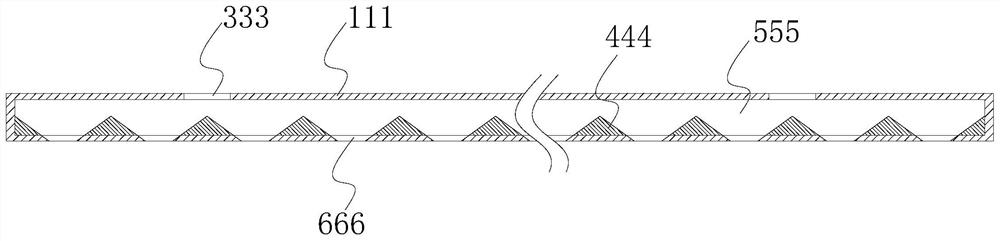
[0031] The spray pipe 4 includes a pipe body 111, a nozzle 222, a liquid inlet 333, an isosceles triangular prism 444, a liquid cavity 555, and a liquid outlet 666. The two ends of the pipe body 111 are closed ends, and the pipe body 111 is closed. The top of 111 is provided with a liquid inlet 333, and the liquid inlet 333 communicates with the liquid chamber 555. The inside of the tube body 111 is evenly distribu...

Embodiment 2

[0036] see Figure 1-9 , the present invention provides a technical solution of a road maintenance vehicle: its structure includes an asphalt spreader 1, a vehicle body 2, a side bracket 3, a spraying pipe 4, a connecting frame 5, and a delivery pipe 6. The two parts of the vehicle body 2 Side brackets 3 are provided on both sides, and an asphalt spreader 1 is arranged on the car body 2. The asphalt spreader 1 is connected to the spray pipe 4 through the delivery pipe 6, and the spray pipe 4 is connected to the spray pipe 4 through the connecting frame 5. Body 2.

[0037] The spray pipe 4 includes a pipe body 111, a nozzle 222, a liquid inlet 333, an isosceles triangular prism 444, a liquid cavity 555, and a liquid outlet 666. The two ends of the pipe body 111 are closed ends, and the pipe body 111 is closed. The top of 111 is provided with a liquid inlet 333, and the liquid inlet 333 communicates with the liquid chamber 555. The inside of the tube body 111 is evenly distribu...


PUM


Abstract

The invention discloses a pavement maintenance vehicle, and the vehicle structurally comprises asphalt distributors, a vehicle body, side supports, a spraying pipe, a connecting frame and a conveyingpipe; the side supports are arranged on the two sides of the vehicle body respectively, the asphalt distributors are arranged on the vehicle body, and the asphalt distributors are connected with the spraying pipe through the conveying pipe. The invention has the beneficial effects that through the arrangement of the pipe body, the spray head, the liquid inlet, the isosceles triangular prism, the liquid cavity and the liquid outlet, asphalt staying on the spray head can be shaken off and vibrated off in time by utilizing the elasticity, the physical inertia principle and the resonance phenomenon of the spring after asphalt spraying is completed each time, and the situation that the spray head is blocked due to the fact that the asphalt remains on the spray head is prevented; the liquid fluxof the nozzle is not affected, the nozzle does not need to be cleaned one by one, the workload of operators can be reduced, the flow regulator is additionally arranged at the bottom of the cover body, and the size of the spraying opening can be adjusted according to the thickness requirements of different layers of pavement laying so as to adjust the amount of asphalt sprayed liquid.

Description

technical field [0001] The invention relates to the technical field of road construction, in particular to a road maintenance vehicle. Background technique [0002] During the use of highways, due to the impact of rolling, impact, wear and weather changes on the road surface, it often causes defects and damage to the road surface. Road surface damage affects the vehicle's driving speed, load capacity, fuel consumption, mechanical wear, and driving comfort, as well as harmful effects on traffic safety and environmental protection. In order to prevent road surface damage and maintain a good technical condition of the road surface, the road surface will be maintained. During the road surface maintenance, asphalt spraying will be carried out. Due to the high viscosity of the asphalt, it will Finally, there is often a small amount of asphalt remaining on the nozzle. If the nozzle is not cleaned in time, the asphalt will form agglomerates and be fixed on the nozzle, which will gre...

Claims


Application Information

Patent Timeline
IPC IPC(8): E01C19/17E01C23/03
CPCE01C19/17E01C19/172E01C19/176E01C23/03
Inventor 陈碧香
Owner 陈碧香
Why Eureka
Try Eureka