Demand-based charging of a heat pipe

Active Publication Date: 2017-04-13
IBM CORP
View PDF10 Cites 3 Cited by
  • Summary
  • Abstract
  • Description
  • Claims
  • Application Information

AI Technical Summary

Benefits of technology

[0007]A heat pipe includes one or more reservoirs of liquid that are closed at lower temperatures and open at higher temperatures. The opening of the reservoirs at higher temperatures caused by higher power levels dynamically increases the amount of liquid in the heat pipe, which increases performance of the heat pipe at higher power leve

Problems solved by technology

However, at lower heat energy rates, the performance of heat pipes that are overcharged or saturated is less than heat pipes that are charged with less liquid.
This same heat pipe will work less efficiently at a lower power, meaning the temperature of the processor will be higher than

Method used


Image

  • Demand-based charging of a heat pipe
  • Demand-based charging of a heat pipe
  • Demand-based charging of a heat pipe

Examples


Example

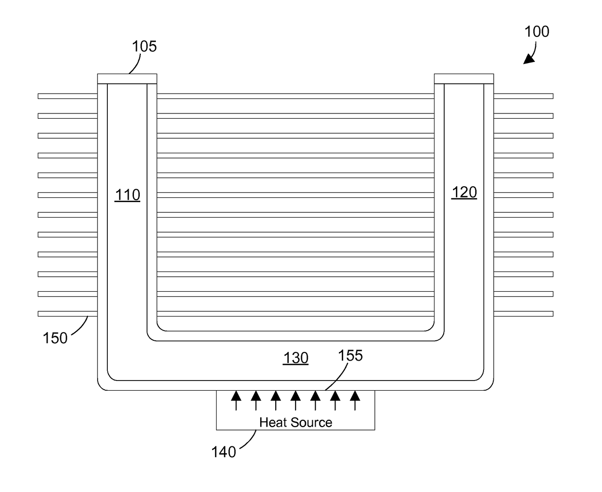
[0017]The disclosure and claims herein relate to a heat pipe that includes one or more reservoirs of liquid that are closed at lower temperatures and open at higher temperatures. The opening of the reservoirs at higher temperatures caused by higher power levels dynamically increases the amount of liquid in the heat pipe, which increases performance of the heat pipe at higher power levels. As the heat pipe cools, the liquid condenses and flows back into the reservoirs. As the heat pipe continues to cool, the reservoirs close. The result is a heat pipe that is more efficient at lower power levels and still maintains high efficiency at higher power levels due to the demand-based charging of the liquid based on temperature.

[0018]Referring to FIG. 1, a heat sink 100 is shown that includes a heat pipe 105 in a U-shape with vertical portions 110 and 120 coupled to a common horizontal portion 130. The horizontal portion 130 is charged with a first quantity of a liquid. The heat sink 100 inc...


PUM


Abstract

A heat pipe includes one or more reservoirs of liquid that are closed at lower temperatures and open at higher temperatures. The opening of the reservoirs at higher temperatures caused by higher power levels dynamically increases the amount of liquid in the heat pipe, which increases performance of the heat pipe at higher power levels. As the heat pipe cools, the liquid condenses and flows back into the reservoirs. As the heat pipe continues to cool, the reservoirs close. The result is a heat pipe that is more efficient at lower power levels and still maintains high efficiency at higher power levels due to the demand-based charging of the liquid based on temperature.

Description

BACKGROUND[0001]1. Technical Field[0002]This disclosure generally relates to heat pipes, and more specifically relates to a heat pipe that includes one or more reservoirs that provide demand-based charging.[0003]2. Background Art[0004]A heat pipe is used to transfer heat between a hot interface and a cold interface. The heat pipe includes a liquid in contact with a thermally conductive solid surface at the hot interface. When the hot interface heats up, the liquid turns into a vapor by absorbing heat from the hot interface. The vapor then travels along the heat pipe to the cold interface and condenses back into liquid, which releases the latent heat. The liquid then returns to the hot interface, and the cycle repeats. Heat pipes are highly effective thermal conductors, with an effective thermal conductivity orders of magnitude larger than for other heat transfer methods, such as a solid metal like copper.[0005]Heat pipes are charged with a liquid. The amount of liquid in the heat pi...

Claims


Application Information

Patent Timeline
IPC IPC(8): F28D15/06
CPCF28D15/06F28D15/0275F28D15/0283F16K31/002F28D2015/0216F28F3/02
Inventor ANDERL, WILLIAM J.ELISON, BRET P.MANN, PHILLIP V.SINHA, ARVIND K.
Owner IBM CORP
Why Eureka
Try Eureka