Recording apparatus and inkjet printer

a recording apparatus and inkjet printer technology, applied in the field of recording apparatus, can solve the problems of ink leakage from the nozzle, inability to properly propagate the pressure wave applied to the ink in the pressure chamber, and increase the pressure of ink in the individual ink channels, so as to reduce liquid consumption and efficiently remove the air existing in the channel

Active Publication Date: 2009-09-03
BROTHER KOGYO KK
View PDF10 Cites 3 Cited by
  • Summary
  • Abstract
  • Description
  • Claims
  • Application Information

AI Technical Summary

Benefits of technology

[0007]A need has arisen for a recording apparatus and an inkjet printer that can efficiently remove air existing in a channel as well as reduce liquid consumption.

Problems solved by technology

When air gets mixed inside the ink supply channel formed in the inkjet head, the pressure waves applied to the ink in the pressure chambers cannot properly propagate through the channels.
However, in the above-described inkjet head, increasing the pressure of ink supplied from the supply port leads to an increase in the pressure of ink in the individual ink channels.
This causes the ink to leak from the nozzles.

Method used


Image

  • Recording apparatus and inkjet printer
  • Recording apparatus and inkjet printer
  • Recording apparatus and inkjet printer

Examples


Embodiment Construction

[0025]Various embodiments, and their features and advantages, may be understood by referring to FIGS. 1-11, like numerals being used for corresponding parts in the various drawings.

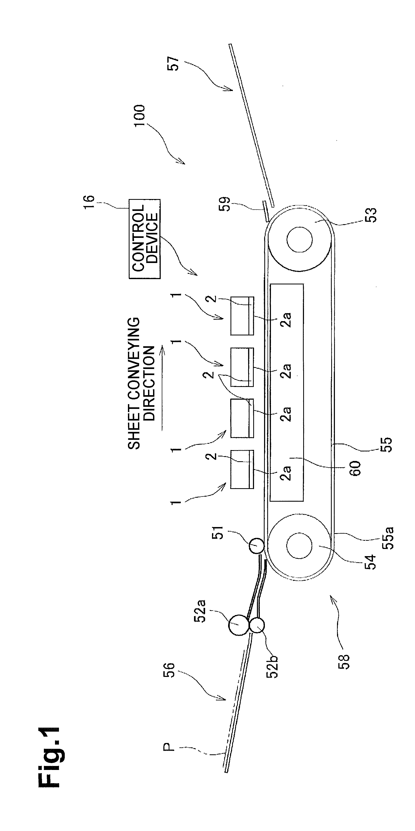
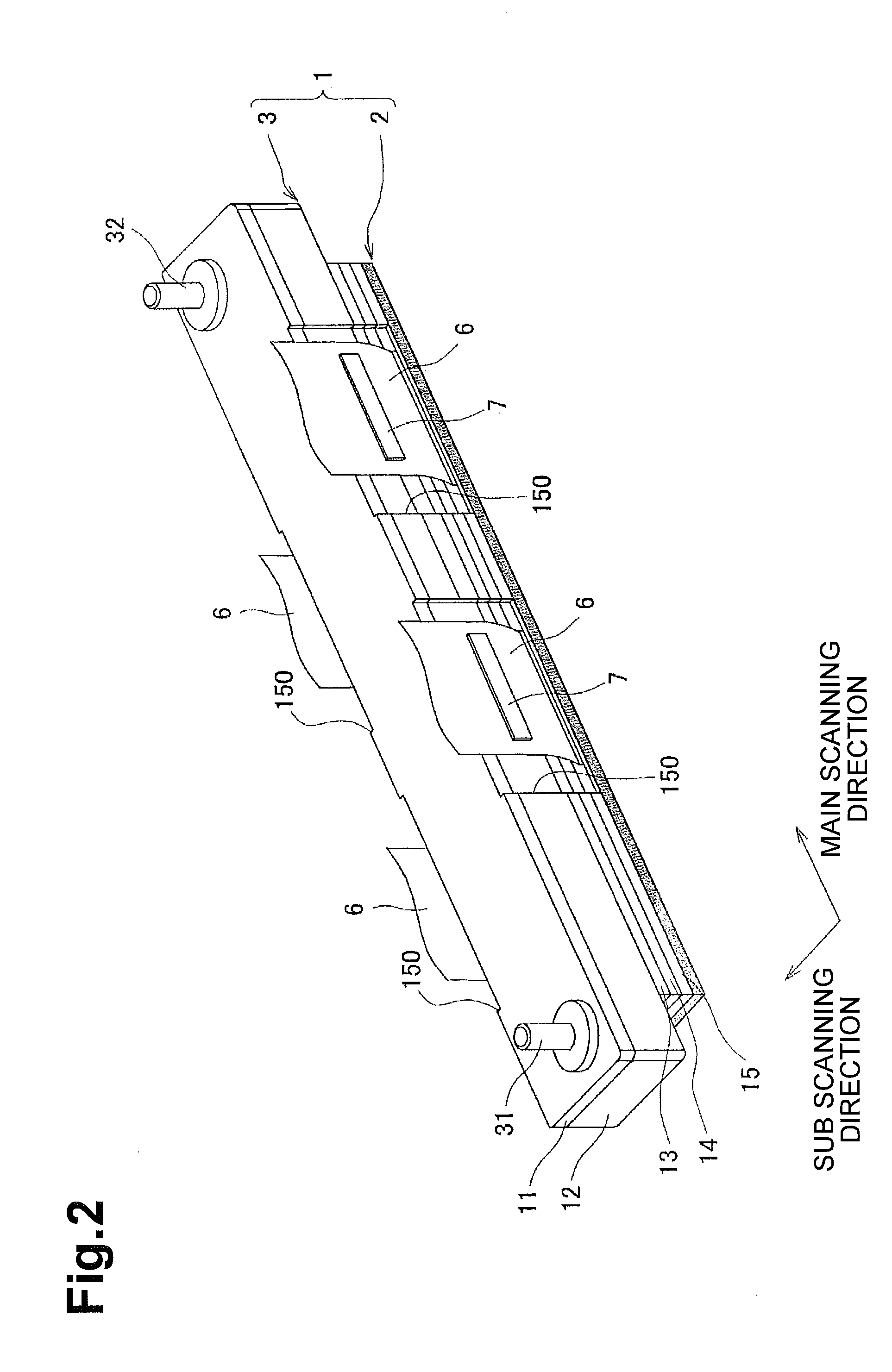
[0026]Referring to FIG. 1, an inkjet printer 100 may be a color inkjet printer including a plurality of, e.g., four, inkjet heads 1. The inkjet printer 100 may also include a feed unit 56 at the left side of the drawing and a discharge unit 57 at the right side of the drawing.

[0027]A sheet conveying path may be positioned inside the inkjet printer 100. A sheet P may be conveyed along the sheet conveying path from the feed unit 56 towards the discharge unit 57. A plurality of, e.g., two, feed rollers 52a and 52b that nip and convey the sheet P may be positioned downstream of the feed unit 56.

[0028]A conveying mechanism 58 may be positioned at a central part of the sheet conveying path. The conveying mechanism 58 may include a plurality of, e.g. two, belt rollers 53 and 54, an endless conveying belt 55 woun...


PUM


Abstract

A recording apparatus may comprise a channel unit comprising a pressure chamber configured to store a liquid, and nozzles. The recording apparatus may comprise a reservoir unit connected to the channel unit and comprising a supply port, a drain port, a supply channel communicating with the channel unit, and a drainage channel branching off from the supply channel and communicating with the outside via the drain port. The recording apparatus may comprise a plurality of actuators configured to apply pressure to the liquid in the pressure chamber. The recording apparatus may comprise a meniscus vibrator configured to drive the actuators to vibrate meniscus produced in the nozzles without causing liquid droplets to be ejected therefrom when the liquid supplied from the supply port is being drained from the drain port after traveling through the supply channel and the drainage channel.

Description

CROSS REFERENCE TO RELATED APPLICATION[0001]This application claims priority to Japanese Patent Application No. 2008-48527, filed on Feb. 28, 2008, the entire subject matter and disclosure of which is incorporated herein by reference.BACKGROUND OF THE DISCLOSURE[0002]1. Field of the Disclosure[0003]The features herein relate to a recording apparatus that records an image on a recording medium by ejecting liquid droplets thereon.[0004]2. Description of the Related Art[0005]A known inkjet head distributes ink supplied from a supply port to a plurality of individual ink channels, which extend from pressure chambers to nozzles, via an ink supply channel and a common ink chamber. The inkjet head also apply pressure to the ink inside the pressure chambers in pulses so as to eject ink droplets from the nozzles communicating with the pressure chambers. When air gets mixed inside the ink supply channel formed in the inkjet head, the pressure waves applied to the ink in the pressure chambers ...

Claims


Application Information

Patent Timeline
Patent Type & Authority Applications(United States)
IPC IPC(8): B41J2/04
CPCB41J2/04596B41J2/04581
Inventor SUZUKI, YOSHIHUMI
Owner BROTHER KOGYO KK
Why Eureka
Try Eureka