Antenna apparatus

a technology of antenna and antenna support, which is applied in the direction of antenna supports/mountings, multi-port networks, transmission, etc., can solve the problems of signal interference or signal fade, phase shift operation of each signal path may have an adverse effect, and the isolation between such rf modules is deteriorated, so as to reduce or prevent problems

Active Publication Date: 2022-07-12
MURATA MFG CO LTD
View PDF21 Cites 0 Cited by
  • Summary
  • Abstract
  • Description
  • Claims
  • Application Information

AI Technical Summary

Benefits of technology

[0005]Preferred embodiments of the present invention provide antenna apparatuses that each significantly reduce or prevent problems, for example, signal interference or signal fade, by significantly reducing or preventing signals from flowing in via a common terminal in a switch simultaneous connection state.
[0011]With the above-described features, the impedance in the second frequency band of the first signal path as seen from the common terminal of the switch is open, and signals input to and output from the second input / output terminal via the second signal path are less likely to be affected by the above-described RF circuit on the first signal path.
[0013]In a preferred embodiment of the present invention, when an area in which a real part of a reflection coefficient is positive and an imaginary part is positive is represented as a first quadrant of a Smith chart, and an area in which the real part of the reflection coefficient is positive and the imaginary part is negative is represented as a fourth quadrant of the Smith chart, in the second frequency band, a round-trip phase change amount between the common terminal and the RF circuit may be a phase change amount in which the reflection coefficient of the first signal path as seen from the common terminal is positioned in the first quadrant or the fourth quadrant of the Smith chart. Accordingly, in the second frequency band, the impedance of the first signal path as seen from the common terminal seems to be high, and signals input to and output from the second input / output terminal of the switch via the second signal path are less likely to be affected by the above-described RF circuit on the first signal path.
[0014]In a preferred embodiment of the present invention, in the second frequency band, a round-trip phase change amount between the common terminal and the RF circuit may be a phase change amount in which an impedance of the first signal path as seen from the common terminal is greater than or equal to about 100Ω. Accordingly, in the second frequency band, the impedance of the first signal path as seen from the common terminal seems to be high, and signals input to and output from the second input / output terminal of the switch via the second signal path are less likely to be affected by the above-described RF circuit on the first signal path.
[0015]According to preferred embodiments of the present invention, antenna apparatuses that each significantly reduce or prevent problems, for example, signal interference or signal fade by significantly reducing or preventing signals from flowing in via a common terminal of a switch in the switch simultaneous connection state is provided.

Problems solved by technology

In the case of connecting RF modules by a switch, even if a filter circuit is adjusted in each of the modules, the phase shift operation of each signal path may have an adverse effect.
In a state where isolation between such RF modules is deteriorated, problems such as signal interference or signal fade occur.

Method used


Image

  • Antenna apparatus
  • Antenna apparatus
  • Antenna apparatus

Examples


Embodiment Construction

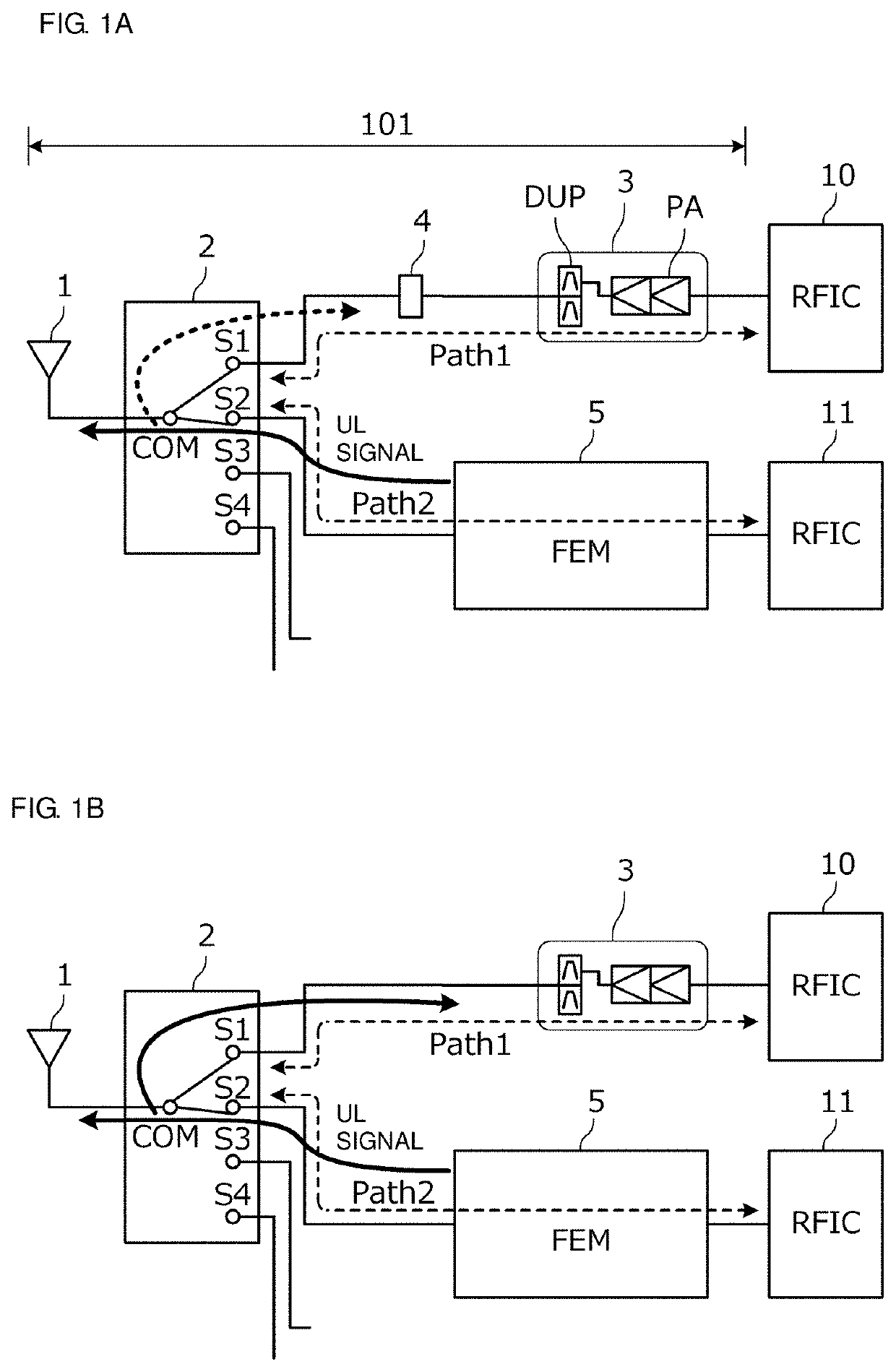
[0030]FIG. 1A is a block diagram showing an antenna apparatus 101 according to a preferred embodiment of the present invention. FIG. 1B is a block diagram showing an antenna apparatus of a comparative example.

[0031]The antenna apparatus 101 shown in FIG. 1A includes an antenna element 1, a switch 2, RFICs 10 and 11, a first signal path Path1, and a second signal path Path2. A power amplifier module 3 and a phase shifter 4 are provided on the first signal path Path1. In addition, a front-end module 5 is provided on the second signal path Path2.

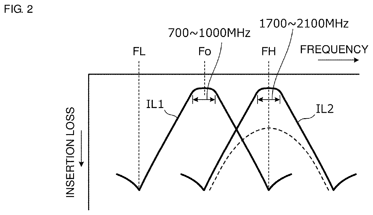
[0032]The antenna element 1 processes signals in a first frequency band and signals in a second frequency band with a frequency band that is different from the first frequency band. In short, the antenna element 1 transmits or receives signals at least in the first frequency band and the second frequency band. The first frequency band is preferably, for example, a frequency band from about 700 MHz to about 1000 MHz, and the second frequency ban...


PUM


Abstract

An antenna apparatus includes an antenna element, a switch with a common terminal that is electrically connected to the antenna element side, a first signal path provided between a first input / output terminal of the switch and a first communication circuit, and a second signal path provided between a second input / output terminal of the switch and a second communication circuit. The first signal path includes a radio-frequency circuit and a phase shifter, and the RF circuit has an impedance that is open or shorted in a second frequency band as seen from the antenna element side. In a state in which the first input / output terminal and the second input / output terminal are both electrically connected to the common terminal, the phase shifter provides a phase shift, and the impedance in the second frequency band of the first signal path as seen from the common terminal is open.

Description

CROSS REFERENCE TO RELATED APPLICATIONS[0001]This application claims the benefit of priority to Japanese Patent Application No. 2018-048018 filed on Mar. 15, 2018 and is a Continuation Application of PCT Application No. PCT / JP2019 / 007730 filed on Feb. 28, 2019. The entire contents of each application are hereby incorporated herein by reference.BACKGROUND OF THE INVENTION1. Field of the Invention[0002]The present invention relates to an antenna apparatus that, in order to support carrier aggregation, electrically connects both of signal paths in two different frequency bands to an antenna with a switch provided therebetween.2. Description of the Related Art[0003]Japanese Unexamined Patent Application Publication No. 2017-98632 describes a radio frequency (RF) module for supporting carrier aggregation, which includes a (simultaneously connectable) switch circuit for connecting a common terminal and both or all of a plurality of input / output terminals, and a matching circuit provided i...

Claims


Application Information

Patent Timeline
Patent Type & Authority Patents(United States)
IPC IPC(8): H04B1/00H01Q1/22H03H7/40H04B1/7075
CPCH01Q1/2208H03H7/40H04B1/70753H04B1/00H04B15/00H04B1/40H03H7/18H03H7/09H01Q3/36
Inventor KOBAYASHI, HIDEAKIISHIZUKA, KENICHI
Owner MURATA MFG CO LTD
Why Eureka
Try Eureka