Eureka AIR delivers breakthrough ideas for toughest innovation challenges, trusted by R&D personnel around the world.

Automatic filter overlap processing and related systems and methods

a filter overlap and processing technology, applied in the field of network monitoring systems, can solve the problems of inability to support only a few span ports, inability to use network hubs in most situations, and inability to obtain data from network sources, etc., to achieve the effect of improving packet forwarding management and control, facilitating sharing access to limited monitoring resources, and improving packet forwarding

Active Publication Date: 2011-12-29
KEYSIGHT TECH SINGAPORE (SALES) PTE LTD
View PDF5 Cites 27 Cited by
  • Summary
  • Abstract
  • Description
  • Claims
  • Application Information

AI Technical Summary

Benefits of technology

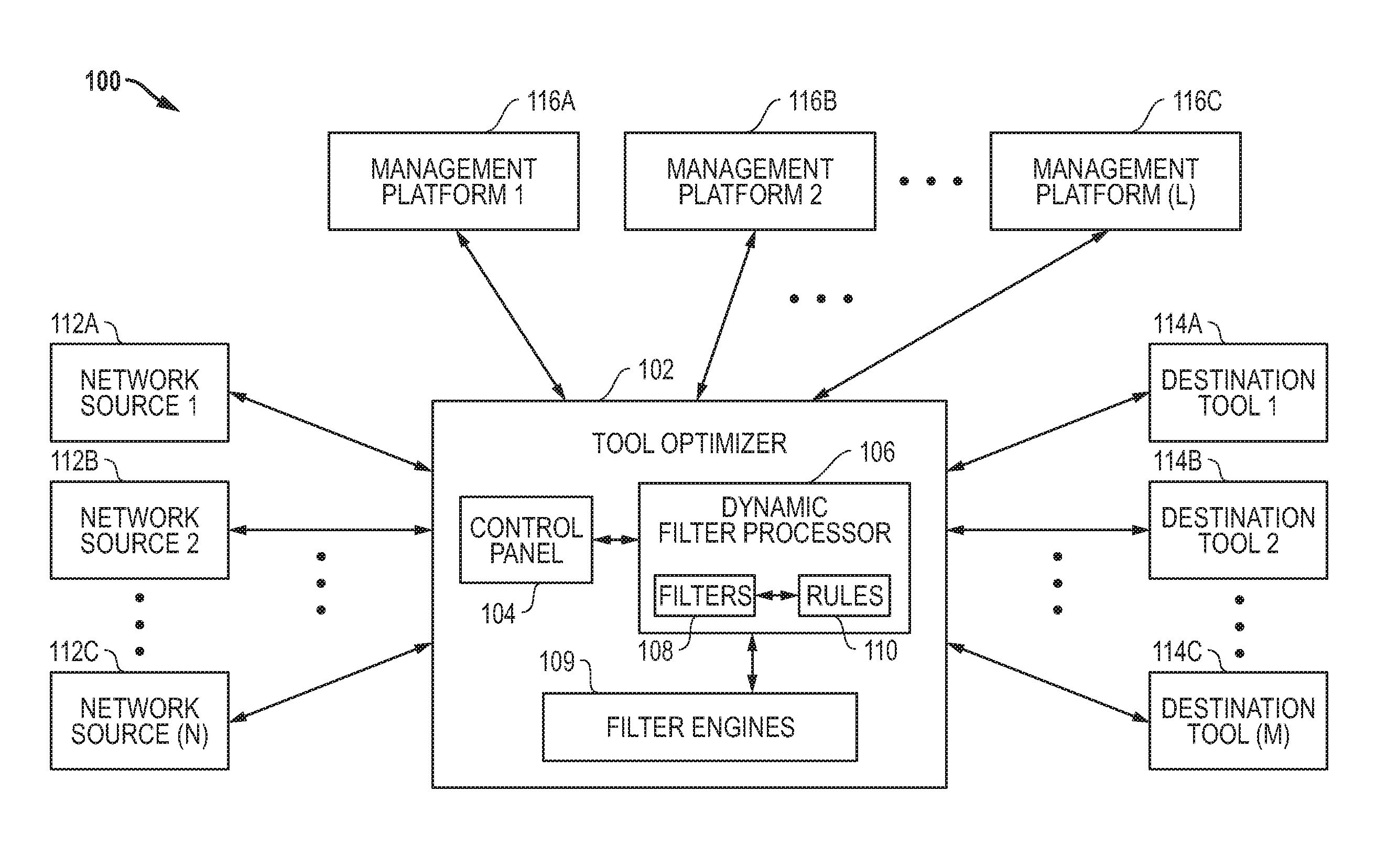
"This patent describes a system and method for managing and controlling packet forwarding in network systems. The system includes a network device with a user interface that allows users to create and modify filters to control how packets are forwarded. The filters can have different forwarding actions, which are automatically identified and applied by the system. The system can also include a dynamic filter processor that analyzes user-defined filters and automatically generates filter rules for the filter engine. The technical effects of this patent include improved management and control of packet forwarding, improved sharing of monitoring resources, and improved network monitoring."

Problems solved by technology

One problem associated with the use of these network monitoring and diagnostic tools in network environments is the complexity of obtaining data from network sources and providing this data to the tools within the network monitoring system.
The hub forces the monitored network segment to operate in half-duplex mode, which makes the use of network hubs impractical for most situations.
The main limitation of SPAN ports is that typical switches support only a few SPAN ports per switch or router.
In addition to the foregoing technical limitations for providing access to network data, an additional consideration is the cost associated with hub, TAP and SPAN port enabled devices that can used to provide the data.
This significant cost along with the growing need for network access and technical limitations of the common access techniques have led to a shortage of access to network data for monitoring purposes.
Because of this limited access, most networks do not have sufficient monitoring points to meet the individual needs of all the network monitoring applications or appliances.
As a result, existing tool aggregation devices have significant limitations for monitoring applications.
However, it has considerable disadvantages with respect to network monitoring systems where it is desirable to forward packets to multiple monitoring tools.
Similar to traditional packet switches / routers, existing tool aggregation devices also continue to be limited to the sequential nature of searching for a single matching rule within a memory such as a TCAM.
As such, downstream instruments may not see all the traffic that they are supposed to see when overlaps exist unless users manually account for the overlaps themselves.
In attempting to account for these overlaps, however, the burden is on the user to understand the filter overlaps and to create filtering criteria and related forwarding actions for each overlap to guarantee that packets are directed to all the desired instrument ports.
Manually generating the filter criteria, however, particularly to handle overlaps, can quickly become a very difficult task, if not practically impossible.
This manual overlap handling is a difficult task because simple overlaps involving independent fields (e.g., destination address field and VLAN field) may not be obvious to users, and more complex filtering criteria may expand into an enormous number of overlaps.
Overlaps, therefore, cannot be readily understood or easily configured / maintained as a manual process.
Further, a manual process is a complex and time consuming task having a greater probability of including errors in setting up the filtering criteria and related forwarding actions.
Further, manually maintaining the filtering criteria is extremely difficult whenever modifications are desired because a user must go back and determine how these modifications will affect the prior filtering criteria manually set up to forward packets.

Method used


Image

  • Automatic filter overlap processing and related systems and methods
  • Automatic filter overlap processing and related systems and methods
  • Automatic filter overlap processing and related systems and methods

Examples


example 1

Overlap Scenario with Two Input Ports

[0175]In the following simple overlap scenario, a user has connected two overlapping filters to Source Port 1 (SP1). Source port 2 (SP2) is connected to one of the filters. Each filter has a list of outgoing ports to send (multicast) its matches. The user wants both filters to send every matching packet to the intended tool ports. The user has set up filtering criteria concerning VLAN addresses and source IP (SIP) addresses to particular outgoing destination ports. The destination ports are represented by “DP#,” and destination ports on another tool optimizer are represented by “B#DP#” (e.g., B2DP1 represents port 1 on box 2). As noted herein, one tool optimizer (box) can be connected to another. For this example, the user has set up the following desired packet forwarding paths:[0176]Connection 1—SP1 packets matching VLAN 5,8 passed to DP4 and B2DP1[0177]Connection 2—SP1 packets matching SIP address range *.*.030.* passed to DP6,7[0178]Connectio...

example 2

Complex Overlap Scenario with One Input Port

[0184]In the following complex overlap scenario, a user has connected five filters to an incoming port (SP1), and each filter has a list of outgoing destination ports to send (multicast) its matches. The user wants all the filters to send every matching packet to the intended instrument ports. As with the first example above, the desired packet forwarding utilizes VLAN and source IP (SIP) traffic-matching criteria. More particularly, for this example, the user has set up the following desired packet forwarding:[0185]Connection 1—SP1 packets matching VLAN 1-4 passed to DP4 and B2DP1[0186]Connection 2—SP1 packets matching VLAN 3-8 passed to DP5,6[0187]Connection 3—SP1 packets matching SIP address range *.*.030.* passed to DP6,7[0188]Connection 4—SP1 packets matching VLAN 9 passed to DP3, 6, 8, 9[0189]Connection 5—SP1 packets matching VLAN 10 passed to DP4

It is noted that the first two connections are overlapping because VLAN 3 and 4 would ma...

example 3

Pass All Optimization Scenario

[0216]The following Pass All optimization scenario compares a situation in which a rule for a Pass All filter is allowed to forward all potentially overlapping packets to destination ports (DPs) and a situation in which Pass All optimization has been applied. It is noted that much less traffic gets sent to the DP6 and DP7 egress buffers below when Pass All optimization is applied.

[0217]When Pass All optimization is applied by the ASE processing, one of the lowest priority entries within the lowest priority ingress engine (e.g., ingress TCAM engine 0) is reserved for each port in the tool optimizer. For instance, if the system supports 28 ports then the lowest 28 TCAM entries in the lowest priority ingress engine are reserved for 28 source port rules. Each of these source port rules is provisioned by default to Drop All, ensuring that any source port packet that does not match another filter rule will be dropped. However, when a user-defined Pass All fil...


PUM


Abstract

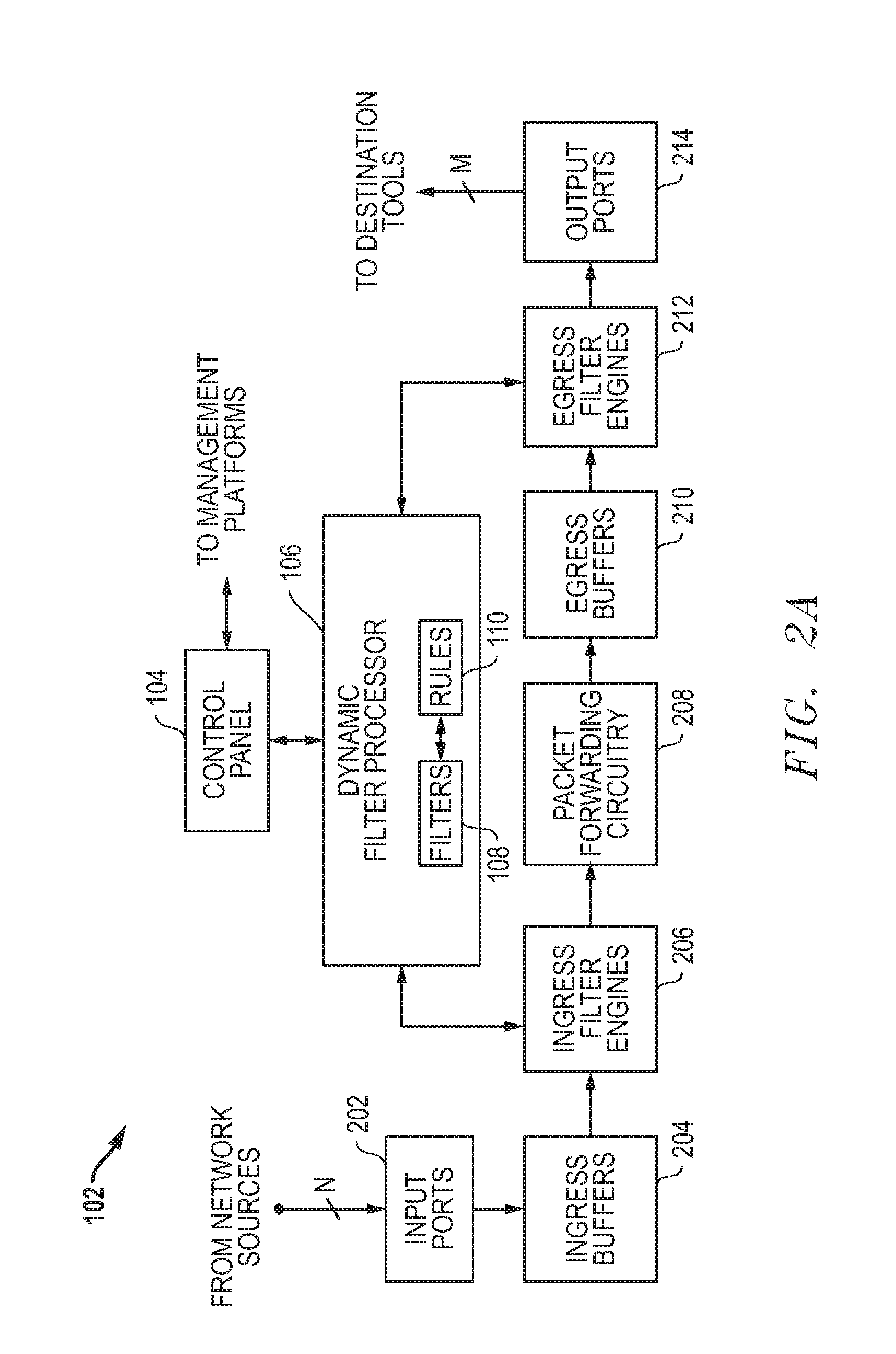
Systems and methods are disclosed that allow for improved management and control of packet forwarding in network systems. Network devices and tool optimizers and a related systems and methods are disclosed for improved packet forwarding between input ports and output ports. The input ports and output ports are configured to be connected to source devices and destination devices, for example, network sources and destination tools in a network monitoring environment. The network devices and tool optimizers disclosed can use a packet processing system whereby forwarding behavior is governed by matching packets in parallel against multiple user-specified packet filtering criteria, and by performing forwarding actions associated with all such matching filter criteria. The multi-action packet forwarding can be implemented using hardware configured to directly provide multi-action packet forwarding and / or hardware configured to provide single-packet-forwarding that has been subsequently configured using filter engines to provide multi-action packet forwarding.

Description

RELATED APPLICATIONS[0001]This application is a continuation application of U.S. patent application Ser. No. 12 / 462,221, filed Jul. 31, 2009, and entitled “AUTOMATIC FILTER OVERLAP PROCESSING AND RELATED SYSTEMS AND METHODS,” which is hereby incorporated by reference in its entirety.[0002]This application is also related in subject matter to the following applications: U.S. patent application Ser. No. 12 / 462,222, entitled “FILTERING PATH VIEW GRAPHICAL USER INTERFACES AND RELATED SYSTEMS AND METHODS,” and U.S. patent application Ser. No. 12 / 462,293, entitled “SUPERSET PACKET FORWARDING FOR OVERLAPPING FILTERS AND RELATED SYSTEMS AND METHODS,” each of which is hereby incorporated by reference in its entirety.TECHNICAL FIELD OF THE INVENTION[0003]This invention relates to network systems and, more particularly, to network monitoring systems that collect and analyze packets associated with network communications.BACKGROUND[0004]Packet-based data networks continue to grow in importance ...

Claims


Application Information

Patent Timeline
Patent Type & Authority Applications(United States)
IPC IPC(8): H04L12/56
CPCH04L43/028H04L49/90H04L45/306
Inventor PLESHEK, RONALD A.WEBB, III, CHARLES A.CHENEY, KEITH E.HILTON, GREGORY S.ABKOWITZ, PATRICIA A.THAKKAR, ARUN K.THAKER, HIMANSHU M.
Owner KEYSIGHT TECH SINGAPORE (SALES) PTE LTD
Why Eureka
Eureka Blog
Learn More