Multiple zone cooling apparatus

a cooling apparatus and multi-zone technology, applied in lighting and heating apparatus, indirect heat exchangers, maintenance and safety accessories, etc., can solve the problems of insufficient chip flushing, subsequent degradation of the surface finish of the component, tool breakage,

Active Publication Date: 2011-12-29
PRATT & WHITNEY CANADA CORP
View PDF1 Cites 43 Cited by
  • Summary
  • Abstract
  • Description
  • Claims
  • Application Information

AI Technical Summary

Problems solved by technology

This machining process is sensitive to the accurate delivery of coolant fluid into the machining zone, as deficiencies in coolant fluid delivery may result in inadequate chip flushing with subsequent degradation of the component's surface finish, tool breakage, and destruction of the component and / or of the machine.

Method used


Image

  • Multiple zone cooling apparatus
  • Multiple zone cooling apparatus
  • Multiple zone cooling apparatus

Examples


Embodiment Construction

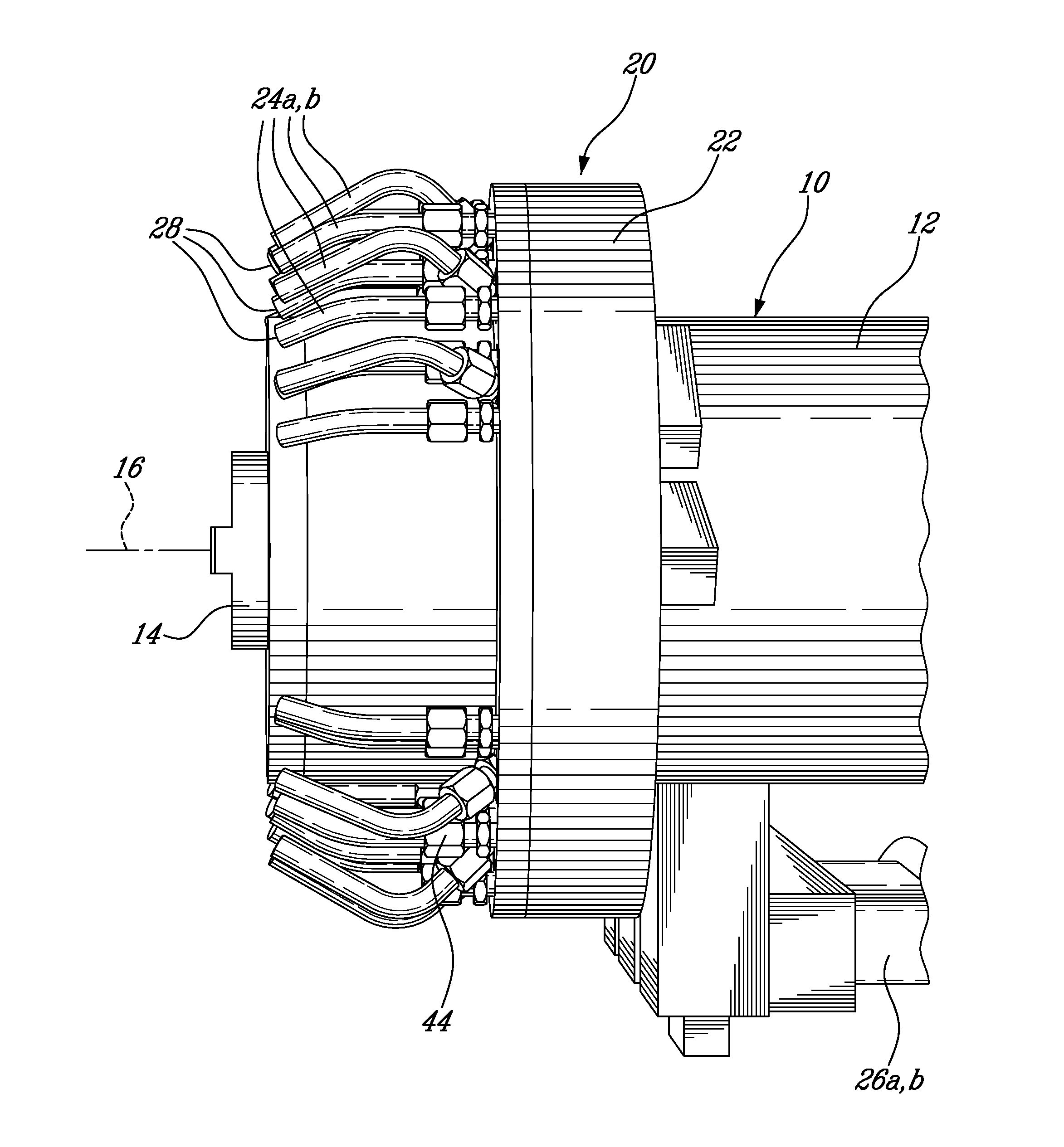
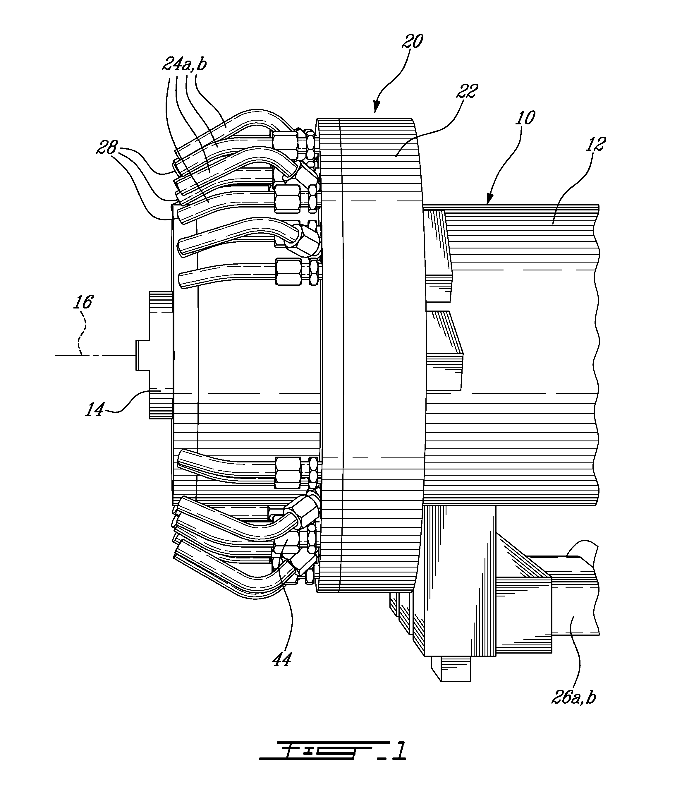
Referring to FIG. 1, a cooling apparatus 20 is installed on a CNC machine 10 (only partially shown). The CNC machine 10 includes a stationary spindle housing 12 supporting a spindle 14, the spindle 14 rotating a selected one of a plurality of cutting tools (not shown).

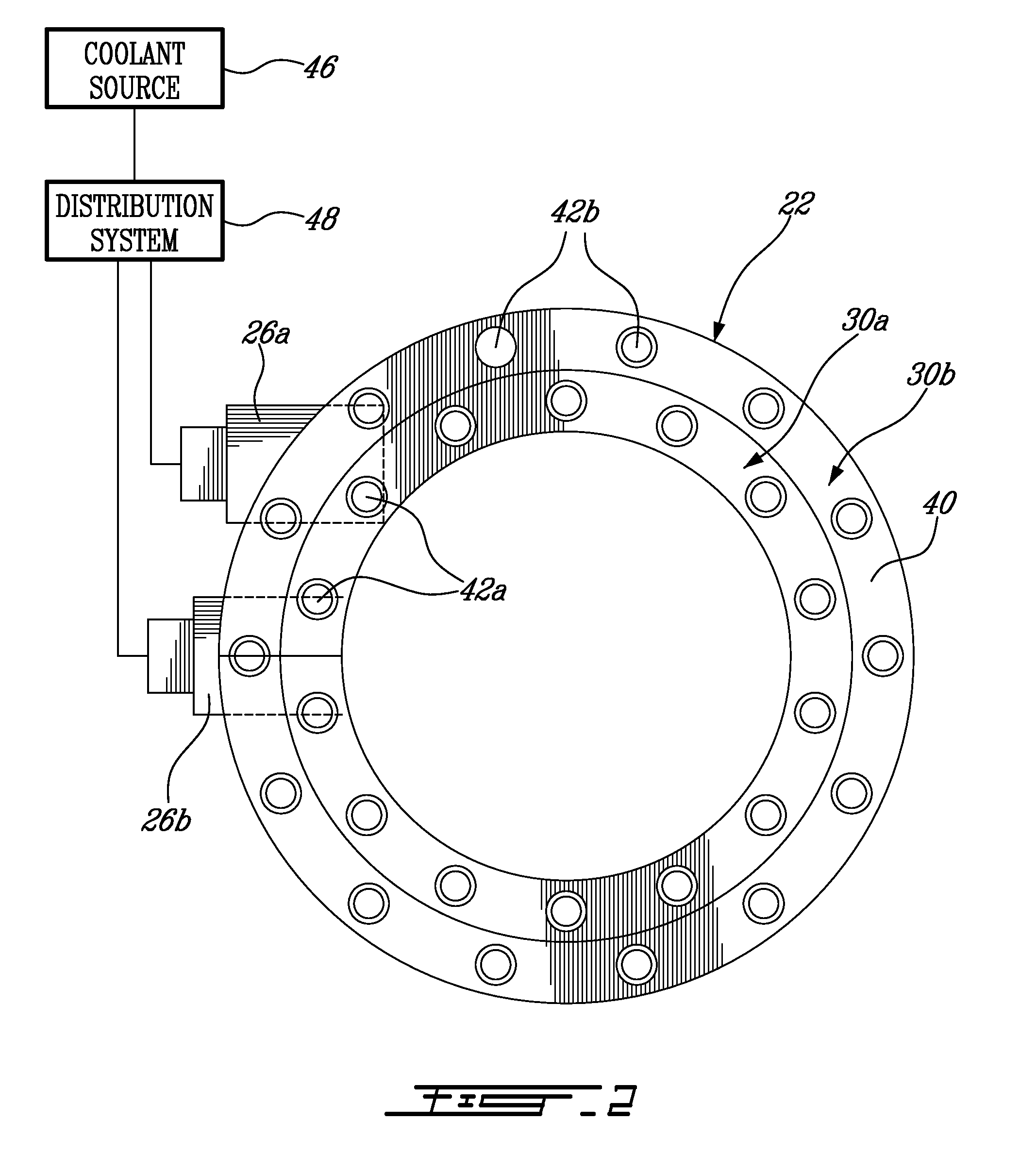
The cooling apparatus 20 includes a ring manifold 22 which is rigidly attached to the spindle housing 12 and from which extend a plurality of coolant fluid nozzles 24a,b. In a particular embodiment, the manifold 22 is slipped over the housing 12 and slid rearwards, and diametrically opposed fasteners, for example screws (not shown), are used to clamp the manifold 22 onto the spindle housing 12 and to center it radially with the spindle's axis of rotation 16. The manifold 22 is located radially by means of rigid inlet conduits 26a,b that extends from the rear of the manifold 22.

Alternately, the manifold 22 can be located radially by any other adequate type of retaining elements, for example by two sheet metal brackets e...


PUM

PropertyMeasurementUnit
lengthaaaaaaaaaa
circumferenceaaaaaaaaaa
of rotationaaaaaaaaaa

Abstract

A cooling assembly for a machine tool including at least first and second nozzle rings mounted on the spindle housing, respectively defining first and second coolant conduits and respectively including first and second pluralities of nozzles in fluid communication with the respective conduit. Each first nozzle is oriented with an outlet thereof directed toward a first machining zone containing cutting edges of at last one tool having a first length. Each second nozzle is oriented with an outlet thereof directed toward a second machining zone different from the first machining zone and containing the cutting edges of at least one tool having a second length.

Description

TECHNICAL FIELDThe application relates generally to CNC machining and, more particularly, to a cooling apparatus for a CNC machine using tools of various gauge lengths.BACKGROUND OF THE ARTMulti-axis CNC (computer numerically controlled) machine tools are often used to produce components, for example gas turbine engine components, machined from solid material. This machining process is sensitive to the accurate delivery of coolant fluid into the machining zone, as deficiencies in coolant fluid delivery may result in inadequate chip flushing with subsequent degradation of the component's surface finish, tool breakage, and destruction of the component and / or of the machine.Components are typically machined using cutting tools of various lengths, usually requiring that the machine operators manually align the machine's coolant delivery nozzles to suit the length of the next tool used. Also, line of sight between the coolant nozzle and the machining zone changes angularly around the cen...

Claims


Application Information

Patent Timeline
Patent Type & Authority Applications(United States)
IPC IPC(8): B23B35/00F28D15/00B23B51/00
CPCB23Q11/10Y10T408/46B23C2250/12B23Q11/1076Y10T409/303752Y10T409/304032Y10T408/03
Inventor LEISHMAN, JAMESATABEY, FUAT
Owner PRATT & WHITNEY CANADA CORP
Why Eureka
Try Eureka