
Off-line channel tuning amplitude slope matched filter architecture

a filter architecture and channel tuning technology, applied in the field of radio communication, can solve the problems of limiting the communication capabilities of the radio system, affecting the quality of the signal, so as to reduce the effect of interferen

Inactive Publication Date: 2011-12-29
BAE SYST INFORMATION & ELECTRONICS SYST INTEGRATION INC
View PDF3 Cites 0 Cited by
  • Summary
  • Abstract
  • Description
  • Claims
  • Application Information

AI Technical Summary

Benefits of technology

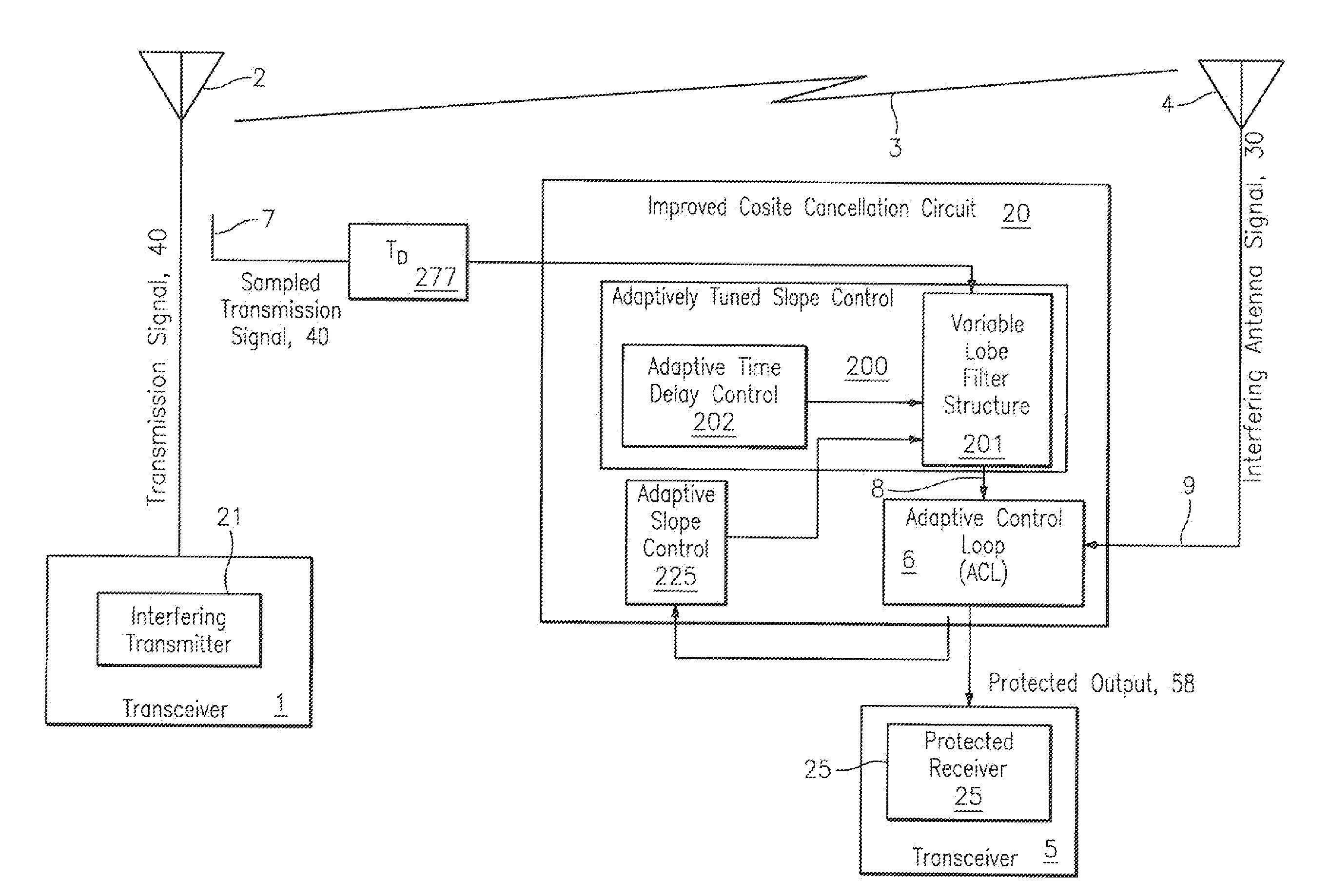
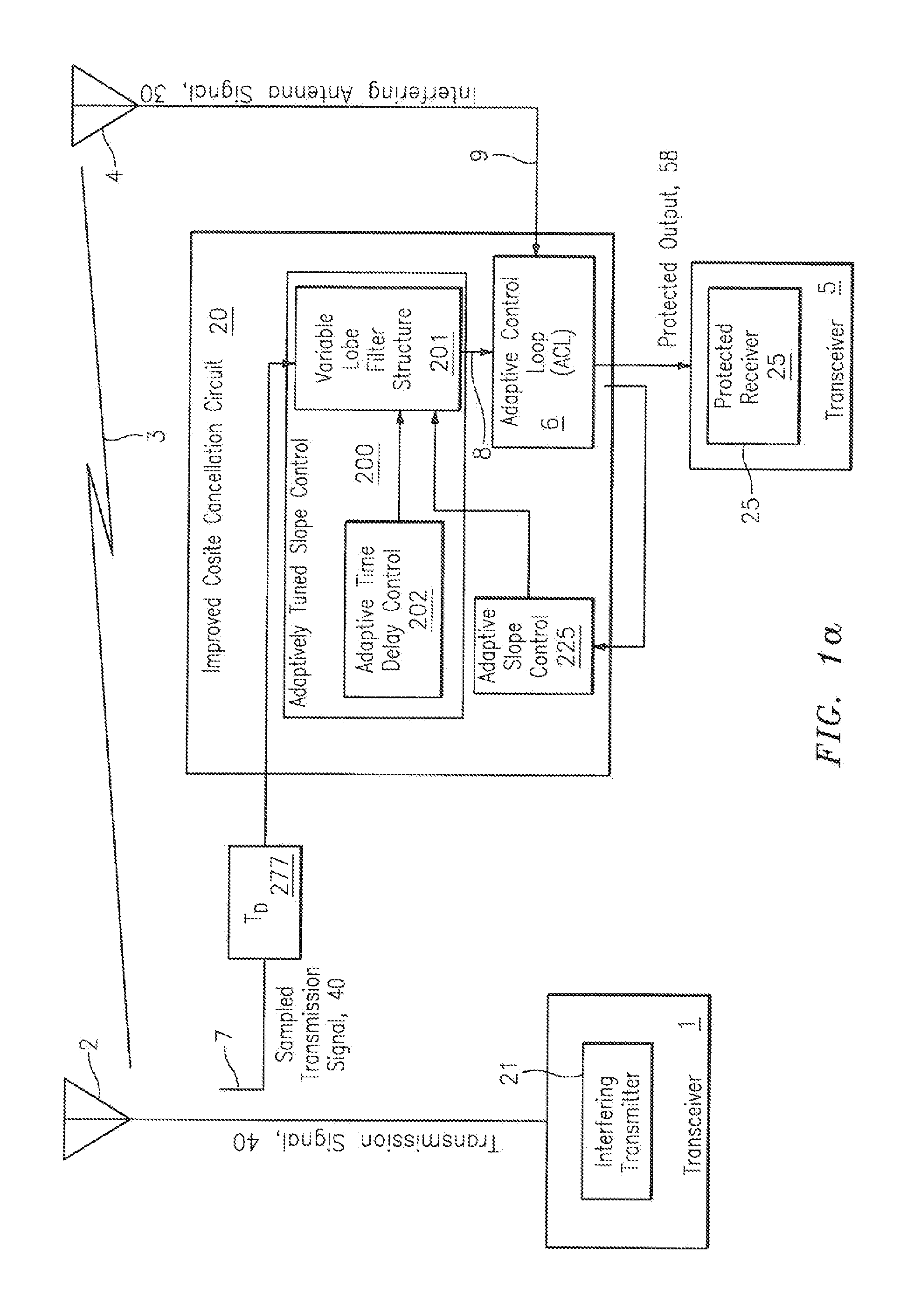
[0014]It is therefore an object of the present disclosure to provide a method and apparatus for reducing the effects of interference between collocated transceivers.
[0016]It is another object of the present disclosure to eliminate the effects of interference between collocated transceivers utilizing interference cancellation.

Problems solved by technology

Each of these manifestations of interference limits the communication capabilities of the radio system afflicted by this problem.
The effects of interference can be some combination of the absence of usable output from a receiver, false signals from a receiver, and malfunction of a device which is operated by the receiver.
During emergency situations, the loss and corruption of the desired signal can be critical.
Unwanted signal interference is generally caused by modulation of signals provided to the receiver by the carrier waves, or by the wideband noise, generated by collocated transmitters.
Unwanted signal interference also occurs when frequency-hopping transmitters are transmitting signals at frequencies that are substantially close to the frequency of the desired receiver signal (i.e., co-channel operation).
Unwanted signal interference can also be caused by “pseudo white-noise” generated by transmitters over a wide band of frequencies on either side of the transmitter's operating frequency.
It is often found in collocated transceiver systems that this “pseudo white-noise” reaches unacceptable levels within the operating band of adjacent receivers.
Unwanted signal interference is also attributed to signals (i.e., spurious emissions) generated by transmitters at odd harmonics of the fundamental frequency of the transmitter output signal.
When the signal noise and spurious sidebands generated by the interfering transmitter are strong, broadband, and scenario dependant, standard interference cancellation is inadequate.
In co-site environments, a collocated source usually interferes with the receiver due to the finite isolation between transmit and receive antennas.
These interference components are received by the collocated radio and degrade system operation.
In practice, however, the two signals are not identical, due to unwanted distortion in the reference path, as well as differences in signal path lengths and non-ideal components in the Tx / Rx signal paths.
Transmission path distortions include time delay, magnitude amplitude and phase distortion, linear amplitude and phase distortion, and quadratic distortion, correction of each adding a level of performance enhancement but also adding to system complexity and difficulty in implementing the corrections.
However, a drawback of the system and method of Kowalski is that it requires information from the transmitter to tune the amplitude slope matching filter and a switch to select the proper filter phasing to operate on a lobe rather than near a null.
However, a drawback of this proposed approach is that it requires dithering the inline tuning value which causes a modulation to be applied to the inline signal, even after the system was converged to an appropriate stable solution.
Dithering the inline tuning value is undesirable because it reduces the achievable nulling and it introduces the dithering noise to the receiver, thus reducing the demodulation achievable.

Method used


Image

  • Off-line channel tuning amplitude slope matched filter architecture
  • Off-line channel tuning amplitude slope matched filter architecture
  • Off-line channel tuning amplitude slope matched filter architecture

Examples


Embodiment Construction

[0039]In the following discussion, numerous specific details are set forth to provide a thorough understanding of the present invention. However, those skilled in the art will appreciate that the present invention may be practiced without such specific details. In other instances, well-known elements have been illustrated in schematic or block diagram form in order not to obscure the present invention in unnecessary detail. Additionally, for the most part, details concerning network communications, electromagnetic signaling techniques, and the like, have been omitted inasmuch as such details are not considered necessary to obtain a complete understanding of the present invention and are considered to be within the understanding of persons of ordinary skill in the relevant art.

[0040]The present description illustrates the principles of the present disclosure. It will thus be appreciated that those skilled in the art will be able to devise various arrangements that, although not expli...


PUM


Abstract

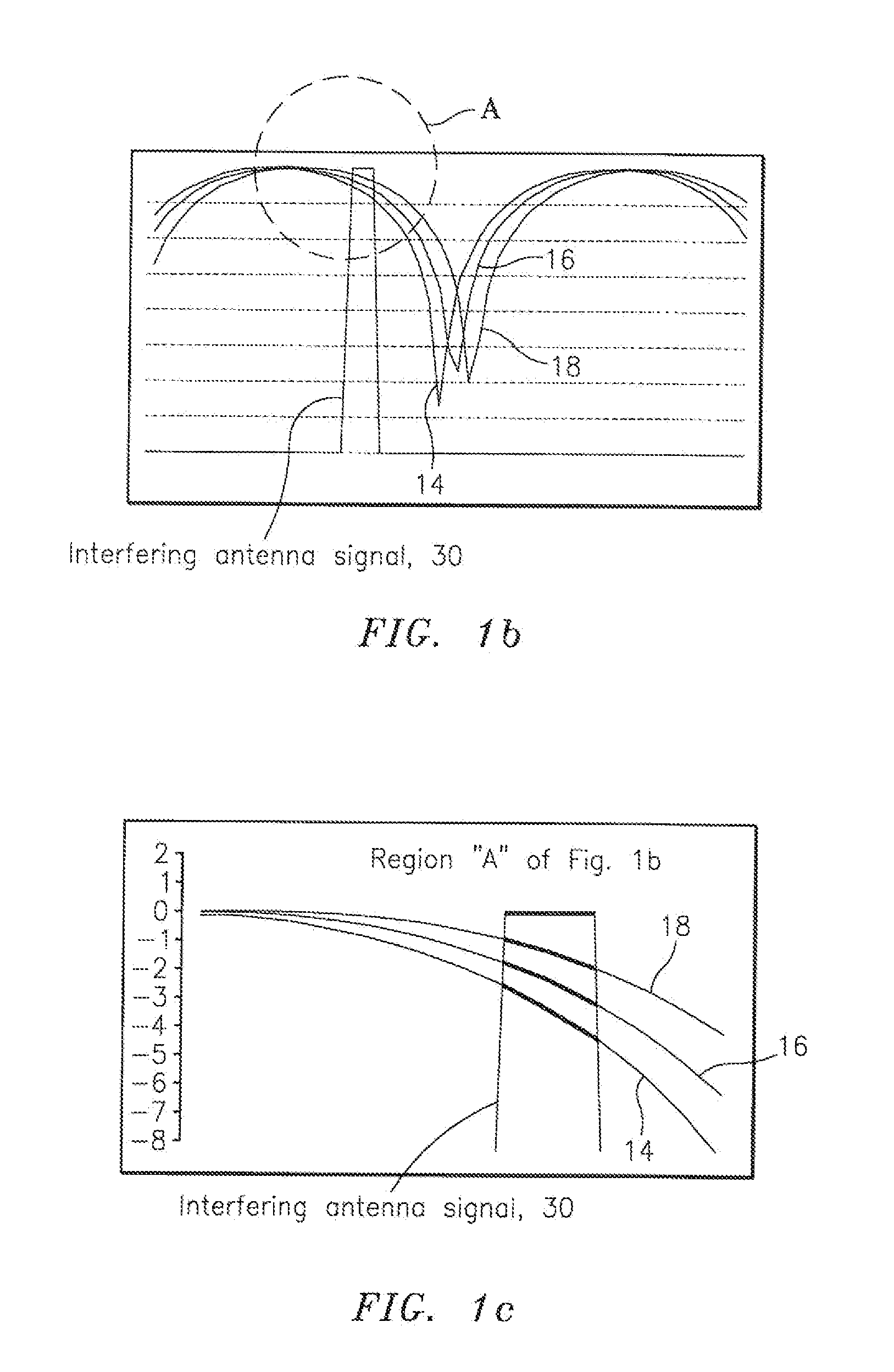
A tuning control system and associated method is provided for continuously and automatically tuning a lobed amplitude slope matching filter (ASMF) to a band center of an interfering signal to provide improved rejection of an interfering signal coupled from a transmission antenna into a local receive antenna in the presence of local multi-path, thereby providing improved interference cancellation system performance. The tuning control system is provided as an element of an interference cancellation system.

Description

CROSS-REFERENCE TO RELATED APPLICATIONS[0001]This Application is a divisional of U.S. application Ser. No. 12 / 315,469 filed Dec. 3, 2008, the contents of which are incorporated herein by reference.FIELD OF THE INVENTION[0002]The invention relates to the field of radio communication and, in particular, to the reduction of interference in signals coupled from a transmission antenna into a local receive antenna in the presence of a local multipath.DESCRIPTION OF THE RELATED ART[0003]Unwanted (i.e., interfering) signals manifest themselves in several ways. Interference can cause a reduction in the sensitivity of a receiver (receiver desensitization), masking of a desired signal, tracking of an undesired interfering signal and loss of the desired signal, and processing of the unwanted interfering signal instead of the desired signal. Each of these manifestations of interference limits the communication capabilities of the radio system afflicted by this problem. The effects of interferenc...

Claims


Application Information

Patent Timeline
Patent Type & Authority Applications(United States)
IPC IPC(8): H04B1/10
CPCH04B1/525H04B1/126
Inventor LACKEY, RAYMOND J.
Owner BAE SYST INFORMATION & ELECTRONICS SYST INTEGRATION INC
Learn More