Protective guard for needles of injection devices

a technology for protecting guards and injection devices, which is applied to infusion devices, intravenous devices, injection needles, etc., can solve problems such as inability to protect needles, inconvenient retraction, and inability to drop or otherwise mishandle equipment, and achieves convenient retraction, prevent unintended pricking, and sufficient robustness.

Inactive Publication Date: 2011-12-29
CHUN THOMAS
View PDF25 Cites 52 Cited by
  • Summary
  • Abstract
  • Description
  • Claims
  • Application Information

AI Technical Summary

Benefits of technology

The patent describes a protective cover for needles that can be used to prevent accidental pricking and control the depth of insertion of the needle. The cover can be provided in different sizes to fit different syringe or needle dimensions. The cover is mobile and can move relatively to the needle, or it can be a sleeve that is axially slidable along the injection device. The cover is locked in place after use to prevent accidental retraction and contamination. The cover also includes a self-closing resilient membrane to further protect the needle when it is not in use.

Problems solved by technology

The technical problem of this patent is to provide a guard arrangement for injection devices to cover sharp points, which can be used to prevent accidental needle sticks and reduce the risk of injury during injection.

Method used


Image

  • Protective guard for needles of injection devices
  • Protective guard for needles of injection devices
  • Protective guard for needles of injection devices

Examples


Embodiment Construction

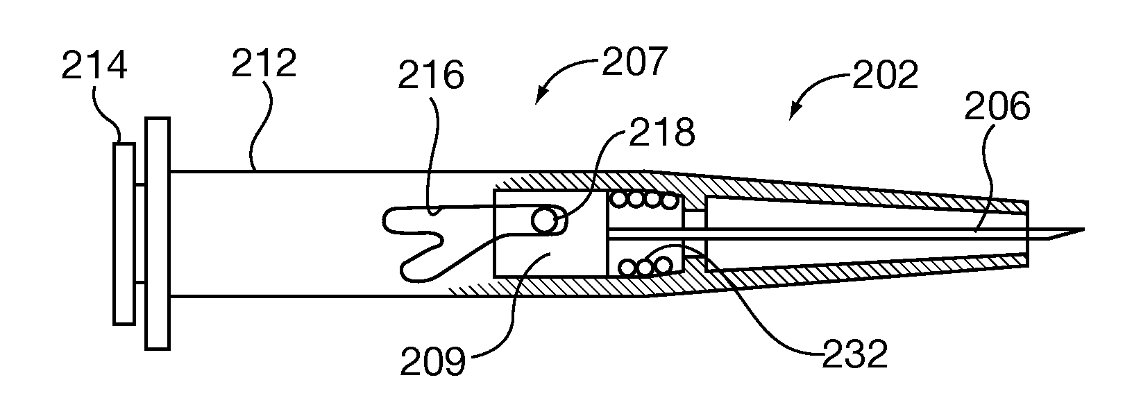
[0052]FIGS. 1-23B show some of the contributing operating principles of the present invention, and are the subject of the prior application of record. This subject matter will be presented herein for the convenience of the reader.

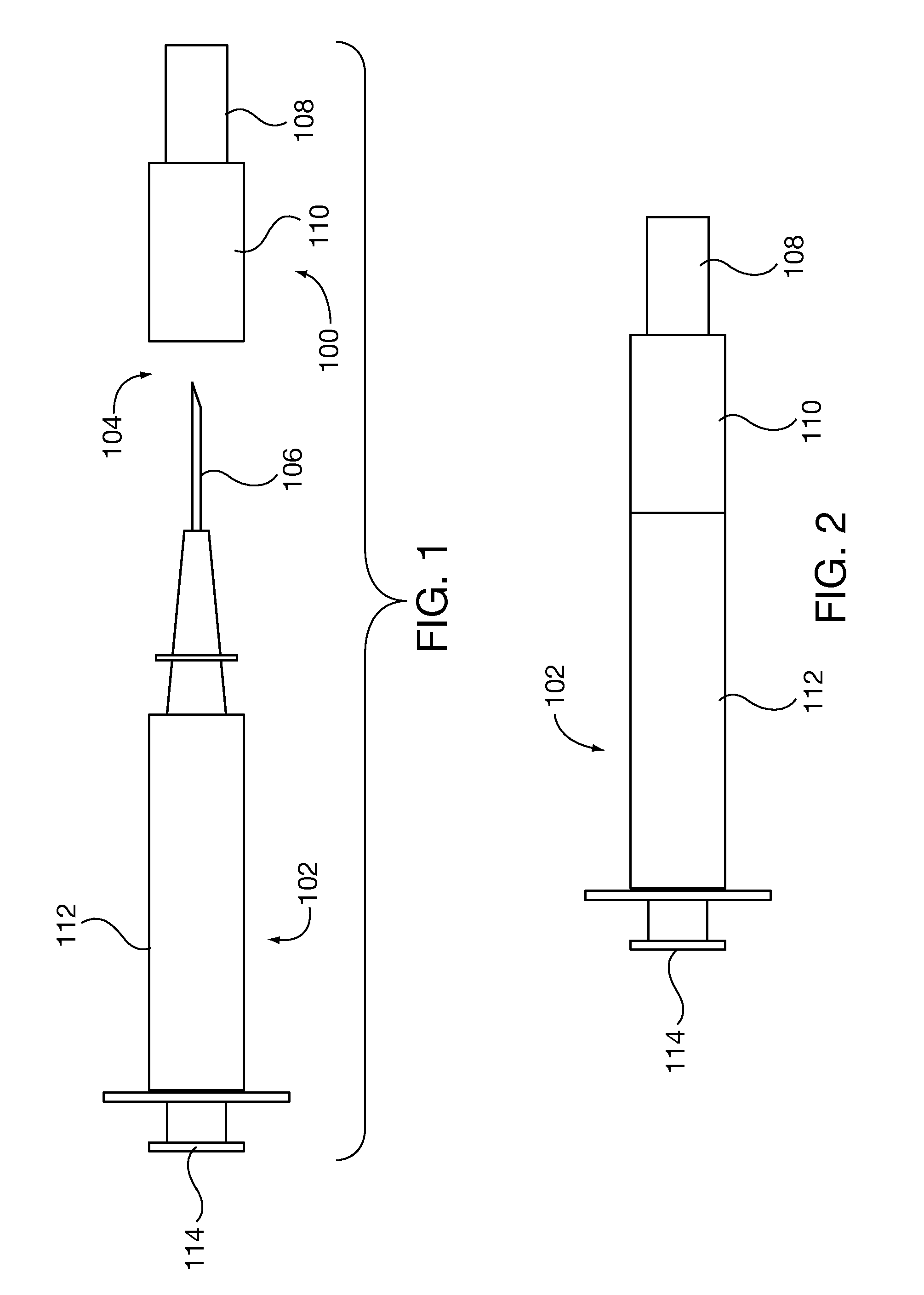
FIG. 1 shows a self-deploying protective cover 100 which is separate from and installable onto an injection device such as a syringe 102, such that the protective cover 100 protects personnel (not shown from the point 104 of the needle 106 of the syringe 102. The protective cover comprises two relatively movable parts: a protective sleeve 108 for covering the needle 106, and a stationary base 110 which engages the syringe 102 and remains stationary relative to the syringe 102. The base 110 may be dimensioned and configured to supportably engage the syringe 102. That is, the base 110 fits to or is connected to the syringe 102 and is supported thereon.

[0053]FIG. 2 shows the base 110 fit to the syringe 102. In the position shown, it will be observed that the n...


PUM


Abstract

A self-deploying cover for protection against unintended pricks from injection devices. The cover comprises a base which engages the injection device, and a protective sleeve which covers the sharp point and moves relative to the base to expose and cover the sharp point. The sleeve is guided by a projection which rides within a generally V-shaped groove formed in the base. The groove comprises deflectable arms which deflect to pass the projection, but which oppose return of the projection after passing. The sleeve is spring urged to the extended position and is automatically withdrawn during injections. After an injection, the sleeve is locked into the extended position by the last deflectable arm.

Description


Claims


Application Information

Patent Timeline
Owner CHUN THOMAS
Why Eureka
Try Eureka