
Board-mating connector with reduced coupling height

a board-mating connector and coupling height technology, which is applied in the direction of securing/insulating coupling contact members, coupling device connections, fixed connections, etc., can solve the problems of poor passive inter-modulation distortion (pimd) characteristics and increase the thickness of the module including the board-mating connector, so as to reduce the thickness of the module to which the board-mating connector is applied, the effect of improving elastic for

Active Publication Date: 2020-06-30
GIGALANE CO LTD
View PDF18 Cites 0 Cited by
  • Summary
  • Abstract
  • Description
  • Claims
  • Application Information

AI Technical Summary

Benefits of technology

The patent text describes a design for a board-mating connector that reduces the coupling height and thickness of the module to which it is applied. It achieves this by hooking a hook bump on a protrusion bump to limit the depth of insertion of the connector, adjusting the gap between the signal portion and the signal electrode, and preventing deformation of the ground electrode. The design also includes an elastic bending portion and elastic restriction portion to further prevent damage and deformation of the ground portion. Additionally, a first elastic portion and a second elastic portion disperse stress applied to the ground elastic portion, and a first elastic portion extending in a horizontal direction to operate, reducing the coupling height.

Problems solved by technology

The board-mating connector increases a coupling height between the upper board and the lower board, and thereby, there is a problem that a thickness of a module including the board-mating connector is increased.
In addition, when a signal portion of the board-mating connector transmits the RF signal through a signal spring, there is a problem that passive inter-modulation distortion (PIMD) characteristics are poor.

Method used


Image

  • Board-mating connector with reduced coupling height
  • Board-mating connector with reduced coupling height
  • Board-mating connector with reduced coupling height

Examples


Embodiment Construction

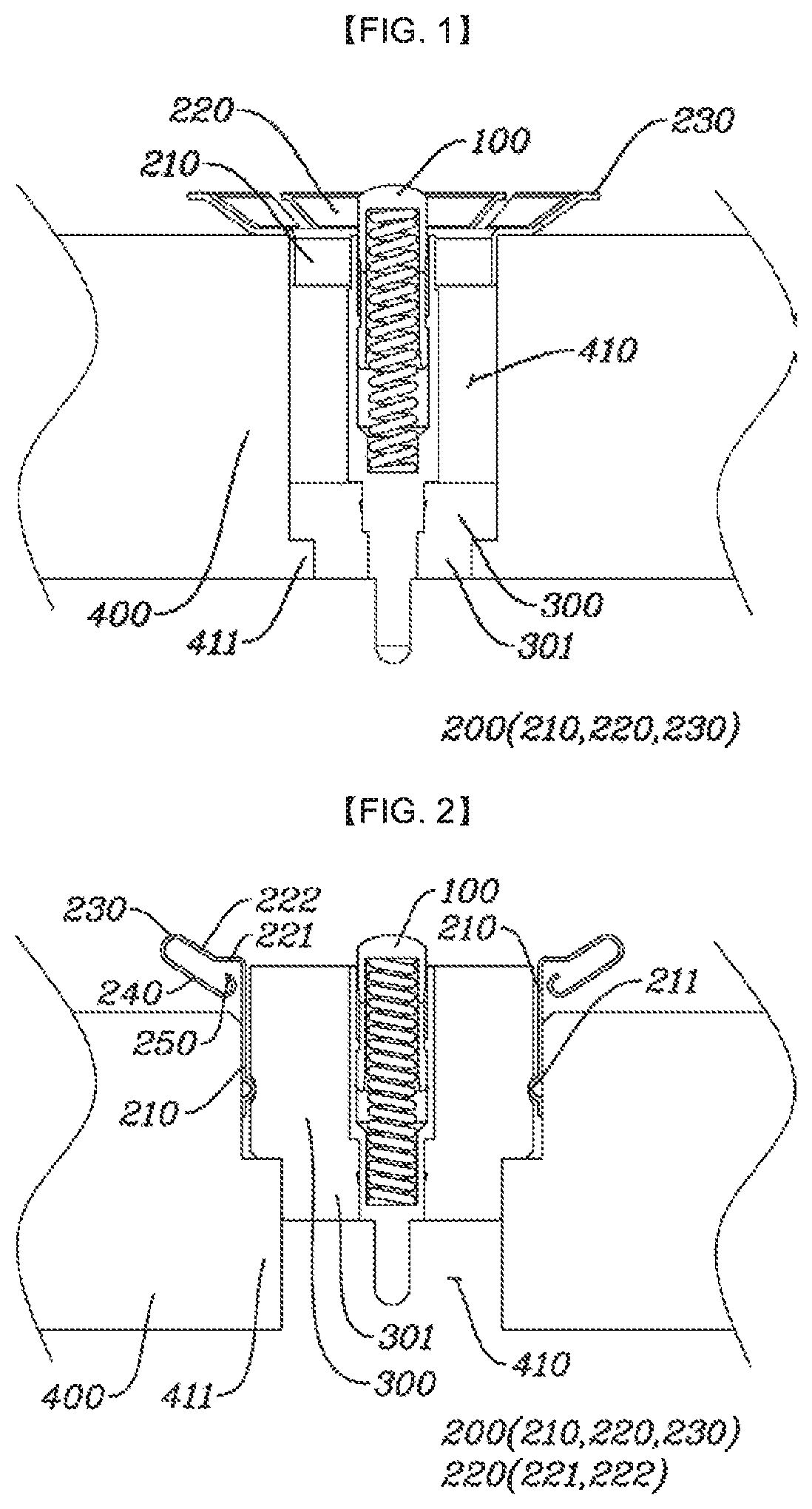
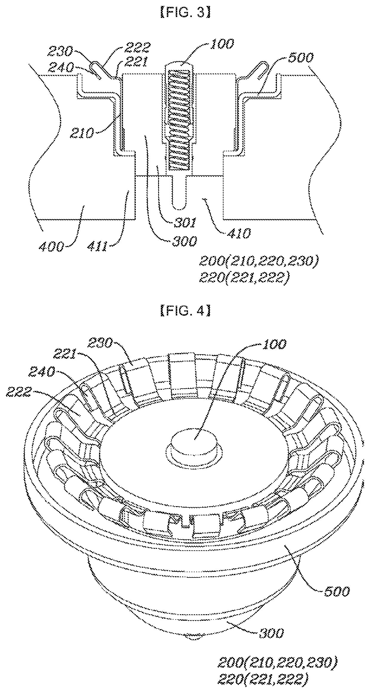
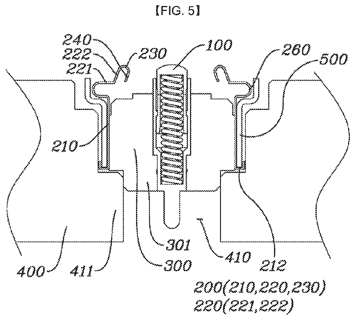
[0045]In order to facilitate understanding of a board-mating connector with a reduced coupling height according to the present invention, each of characteristics will be first described as follows.

[0046]First, the first embodiment is characterized in that a dielectric portion 300 is spaced apart from a ground portion 200 and is located between a signal portion 100 and a housing portion 400.

[0047]In addition, second to fifth embodiments are characterized in that the dielectric portion 300 is located between the signal portion 100 and the ground portion 200.

[0048]In addition, the first to fifth embodiments are characterized in that the embodiments are each distinguished according to a shape of the ground portion 200.

[0049]That is, it is characterized that the first embodiment is a basic embodiment, a ground elastic portion 220 includes a first elastic portion 221 and a second elastic portion 222 in the second to fifth embodiments, the second embodiment further includes an elastic rest...


PUM


Abstract

A board-mating connector with a reduced coupling height includes a signal portion having one side in contact with a signal electrode of a board and to be electrically connected to the signal electrode; a ground portion having one side in contact with a ground electrode of the board to be electrically connected to the ground electrode and having a hollow inside; a housing portion in which a housing insertion hole is formed such that the signal portion and the ground portion are inserted thereinto and in which at least a part of a portion coming into contact with the ground portion is formed of metal; and a dielectric portion which is inserted into the housing insertion hole and is located between the signal portion and the housing portion such that the signal portion is spaced apart from the ground portion and the housing portion.

Description

CROSS-REFERENCE TO RELATED APPLICATIONS[0001]This application claims the benefit under 35 U.S.C. § 119 of Korean Patent Application No. 10-2018-0080103 filed on Jul. 10, 2018 and Korean Patent Application No. 10-2018-0089973 filed on Aug. 1, 2018 in the Korean Intellectual Property Office. The disclosures of both applications are hereby incorporated herein by reference in their entireties.TECHNICAL FIELD[0002]The present invention relates to a board-mating connector with a reduced coupling height.BACKGROUND ART[0003]A board-mating connector transmits an RF signal to a board between an upper board and a lower board, which are formed with signal wires, such as printed circuit boards.[0004]The board-mating connector increases a coupling height between the upper board and the lower board, and thereby, there is a problem that a thickness of a module including the board-mating connector is increased.[0005]In addition, when a signal portion of the board-mating connector transmits the RF si...

Claims


Application Information

Patent Timeline
Patent Type & Authority Patents(United States)
IPC IPC(8): H01R12/71H01R12/70H01R24/52H01R12/52
CPCH01R12/714H01R12/52H01R12/7023H01R24/52H01R13/46H01R13/40H01R13/652H01R12/73H01R12/7082H01R13/2421H01R13/6594H01R24/50H01R2103/00H01R13/648
Inventor SONG, HWA YOONSEO, SANG MINKIM, EUN JUNGLEE, JIN UKJUNG, KYUNG HUNJUNG, HEE SEOK
Owner GIGALANE CO LTD
Learn More