Automated camera cleaning system

a camera cleaning and automatic technology, applied in the field of automatic camera cleaning systems, can solve the problems of obstructing the forward-looking field of the camera, affecting the remote operation of affecting the operation of the camera on the high-speed moving target,

Inactive Publication Date: 2012-01-05
RAYTHEON CO
View PDF34 Cites 129 Cited by
  • Summary
  • Abstract
  • Description
  • Claims
  • Application Information

AI Technical Summary

Problems solved by technology

The airborne debris may accumulate over the camera lens, obstruct the camera's forward-looking field-of-view, and thereby interfere with remote-operation of the high speed moving target.
Manual cleaning of a camera deployed onboard a high speed moving target can be a cumbersome and time-consuming process, which may require that a technician or other personnel member depart from a safe zone, travel several miles to the location at which the high speed vehicles are being operated, manually clean the camera lens, and then again travel several miles to return to the safe zone.
Similar inconveniences are also entailed in the manual cleaning of cameras deployed onboard other remotely-operated vehicles and robots including, for example, Unmanned Airborne Vehicles included within Unmanned Aircraft Systems.
While generally satisfactory for usage in conjunction with stationary photo-enforcement cameras, such externally-mounted wiper systems are generally unsuitable for deployment onboard remotely-controlled vehicles and robots of the type described above.
As the wiper blade clears debris from the outer surface of the transparent pane, the wiper blade temporarily obstructs the camera's field-of-view.
When the camera is utilized to provide a remotely-located operator with a nearly instantaneous or “real-time” video feed, temporary obstruction of the camera's field-of-view can be distracting to the remote operator and may be unacceptable in certain mission scenarios.
Furthermore, externally-mounted wiper systems of the type described above only intermittently clear away debris deposited over the camera lens.
As a result, conventional wiper systems may not clear away debris with sufficient efficiency in scenarios wherein a large amount of debris is suddenly deposited over the camera lens due to, for example, a neighboring detonation.
While the frequency with which the wiper blade sweeps across the transparent panel can be increased, this results in a corresponding increase in the frequency with the wiper blade obstructs the camera's field-of-view.

Method used


Image

  • Automated camera cleaning system
  • Automated camera cleaning system
  • Automated camera cleaning system

Examples


Embodiment Construction

[0008]The following Detailed Description is merely exemplary in nature and is not intended to limit the invention or the application and uses of the invention. Furthermore, there is no intention to be bound by any theory presented in the preceding Background or the following Detailed Description. As appearing herein, the term “camera” is utilized in a broad sense to denote any optical sensor that detects radiation within the visible, infra-red, or other band of the electromagnetic spectrum including, but not limited to, daytime and nighttime video cameras, synthetic aperture radar sensors, and infrared (e.g., thermographic) cameras.

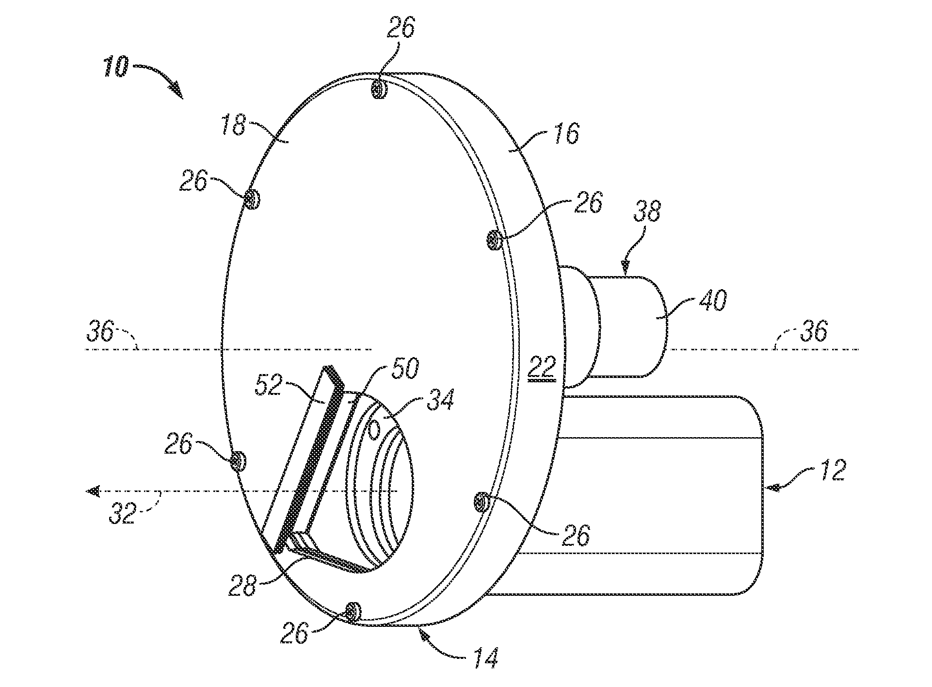
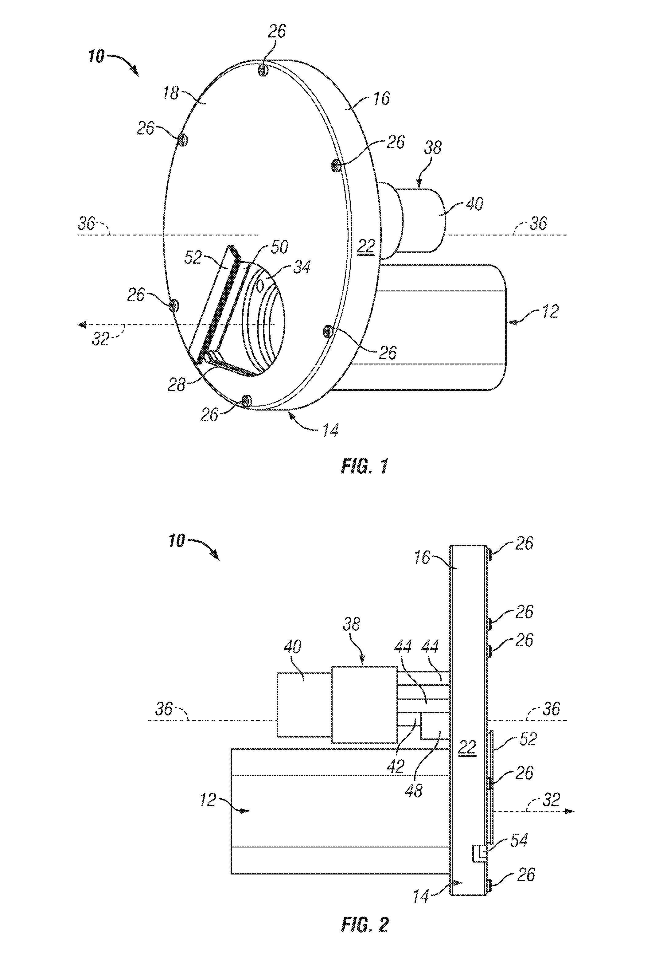
[0009]FIGS. 1 and 2 are isometric and side views, respectively, of an automated camera cleaning system 10 in accordance with an exemplary embodiment. As will be explained more fully below, automated camera cleaning system 10 continually removes dust and other debris that accumulates over the lens of a camera without obstructing the camera's field-of-view....


PUM


Abstract

Embodiments of an automated camera cleaning system are provided. In one embodiment, the automated camera cleaning system includes an optical path, an optically-transmissive lens shield through which the optical path extends, a housing in which the optically-transmissive lens shield is at least partially disposed, and a motor coupled to the lens shield. When energized, the motor moves the optically-transmissive lens shield relative to the housing to vary the region of the optically-transmissive lens shield positioned in the optical path.

Description

TECHNICAL FIELD[0001]The following disclosure relates generally to autonomous camera systems and, more particularly, to embodiments of an automated camera cleaning system well-suited for deployment onboard a remotely-operated robot or vehicle.BACKGROUND[0002]Video cameras and other optical imaging devices are often deployed onboard remotely-controlled vehicles, robots, and the like to provide streaming video feeds to one or more remotely-stationed operators. For example, commercial passenger vehicles utilized during military targeting maneuvers (commonly referred to as “high speed moving targets”) are commonly retrofitted with at least one video camera, a wireless transceiver, and other specialized equipment, which enable remotely-stationed personnel to operate the vehicle in a desired manner High speed moving targets are often operated in flat, dry areas (e.g., dried lake beds or desert terrains), which tend to release large amounts of dust and other debris into the air as the grou...

Claims


Application Information

Patent Timeline
Patent Type & Authority Applications(United States)
IPC IPC(8): B08B7/00
CPCG03B11/00G03B17/568H04N5/225G03B17/08G03B17/56H04N23/00
Inventor LAYTON, JACOB KYLE
Owner RAYTHEON CO
Why Eureka
Try Eureka