Automatic locking/unlocking apparatus for a drawer

a technology for automatic locking and unlocked locks, applied in the field of drawers, can solve the problems of sliding rails or the inevitable damage of automatic locking apparatuses

Inactive Publication Date: 2012-01-05
SUN CHAIN METAL IND
View PDF26 Cites 20 Cited by
  • Summary
  • Abstract
  • Description
  • Claims
  • Application Information

AI Technical Summary

Benefits of technology

[0008]The primary objective of the present invention is to provide an automatic locking / unlocking apparatus for a drawer which can prevent the slide rails or itself from being damaged when the drawer in the locking state is pulled by a large force besides automatically performing the locking or unlocking operation by pressing.
[0009]The secondary objective of the present invention is to provide an automatic locking / unlocking apparatus for a drawer which can prevent the drawer body or itself from being damaged when the drawer in the locking state is pulled by the large force besides automatically performing the locking or unlocking operation by pressing.

Problems solved by technology

However, no matter how the unlocking or locking apparatus for drawer slide rails are designed, they have a common defect that the user cannot tell if the drawer is in a locking or an unlocking state from the outside, so that once the user pulls the drawer which is in the locking state by a large force accidentally, the slide rails or the automatic locking apparatus will be damaged inevitably.

Method used


Image

  • Automatic locking/unlocking apparatus for a drawer
  • Automatic locking/unlocking apparatus for a drawer
  • Automatic locking/unlocking apparatus for a drawer

Examples


first embodiment

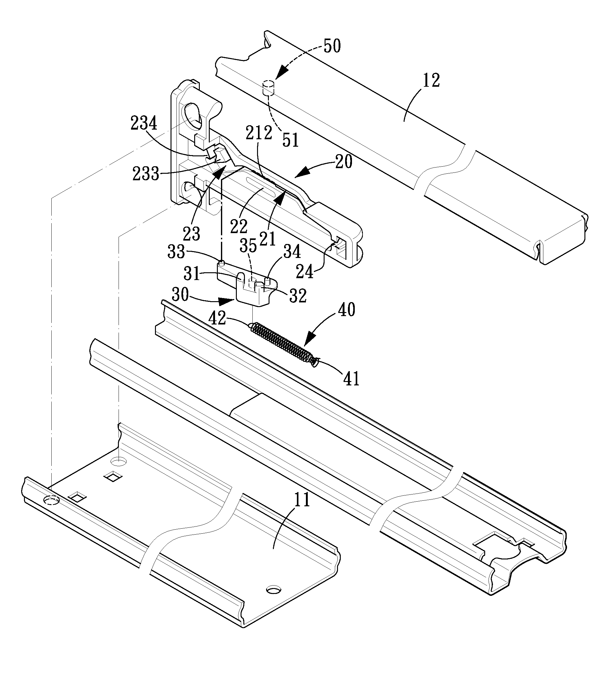
[0037]Referring to FIGS. 3-5, an automatic locking / unlocking apparatus for a drawer in accordance with the present invention is applicable to be assembled on a fixed slide rail 11 and a slidable slide rail 12 and comprises a drive element 50, a main body 20, a slide block 30 and a spring 40.

[0038]The drive element 50 is formed on the slidable slide rail 12 and includes a drive portion 51.

[0039]The main body 20 is fixed on the fixed slide rail 11 in the direction as shown in FIG. 3. The main body 20 includes a rail groove 21, a bar hole 212 formed in a bottom surface 211 of the rail groove 21, a deformation hole 22 which is formed above the bar hole 212 and will deform when being pressed, an annular guide groove 23 in communication with the rail groove 21, and an engaging portion 24. Furthermore, the rail groove 21 includes a transverse first groove section 213, a second groove section 214 bent toward an upper-left direction from a first end of the first groove section 213, and a thi...

second embodiment

[0051]The automatic locking / unlocking apparatus in accordance with the present invention is applicable to be assembled on the drawer body 71 and a drawer cabinet 72. The drive element 61 is disposed on an external surface of the drawer body 71 and also includes a drive portion 611. The main body 62 is fixed on an inner surface of the drawer cabinet 72 and also includes a rail groove 621, a deformation hole 622 which is formed above the bar hole 212 and pressed to deform, an annular guide groove 623 in communication with the rail groove 621, and an engaging portion 624. Thereby, when the drawer is in the locking state, pulling the drawer body 71 with a large force cannot damage the drawer body 71 or the automatic locking apparatus either.


PUM


Abstract

An automatic locking / unlocking apparatus for a drawer is applicable to be assembled on a fixed slide rail and a slidable slide rail of a drawer or on a drawer body and a drawer cabinet. The automatic locking / unlocking apparatus comprises a drive element disposed on the slidable slide rail or the drawer body, a main body fixed on the fixed slide rail or the drawer cabinet, a slide block slidably disposed on the main body, and a spring disposed between the main body and the slide block. By such arrangements, when the drawer is pulled by a large force, it can prevent the slide rails, the drawer body or the automatic locking / unlocking apparatus from being damaged

Description

BACKGROUND OF THE INVENTION[0001]1. Field of the Invention[0002]The present invention relates to a drawer, and more particularly to an automatic locking / unlocking apparatus for a drawer.[0003]2. Description of the Prior Art[0004]Referring to FIG. 1, a first conventional automatic unlocking apparatus for drawer slide rails is provided with a top fastener 83 and a fastening element 54 on an external slide rail 81 and an inner surface of a pull rod 82. The top fastener 83 includes a main body 832 and loading plate 831 centrally extending along one side the main body 832. The main body 832 is provided at each of two opposite sides thereof with a protruding cylinder 8321 on which an elastic element 85 is mounted. A fixing fastener 86 is mounted on the loading plate 831 and provided with a hook (not shown) on the inner surface thereof, and a guiding cylinder 861 at a distal end thereof. The hook is movably engaged in the main body 832. A sliding sleeve assembly 87 is provided at both ends...

Claims


Application Information

Patent Timeline
Patent Type & Authority Applications(United States)
IPC IPC(8): E05C1/08
CPCA47B88/0477A47B88/463Y10T292/03Y10T292/097Y10T292/54
Inventor JUAN, TENG-YICHEN, SHIH-WANG
Owner SUN CHAIN METAL IND
Why Eureka
Try Eureka