
Vehicle Seat

a technology for vehicles and seats, applied in the field of vehicles seats, can solve problems such as implementing a shock absorption structure, and achieve the effects of raising shock absorption properties, good impact energy absorption, and sufficient rigidity

Inactive Publication Date: 2012-01-05
NHK SPRING CO LTD
View PDF12 Cites 7 Cited by
  • Summary
  • Abstract
  • Description
  • Claims
  • Application Information

AI Technical Summary

Benefits of technology

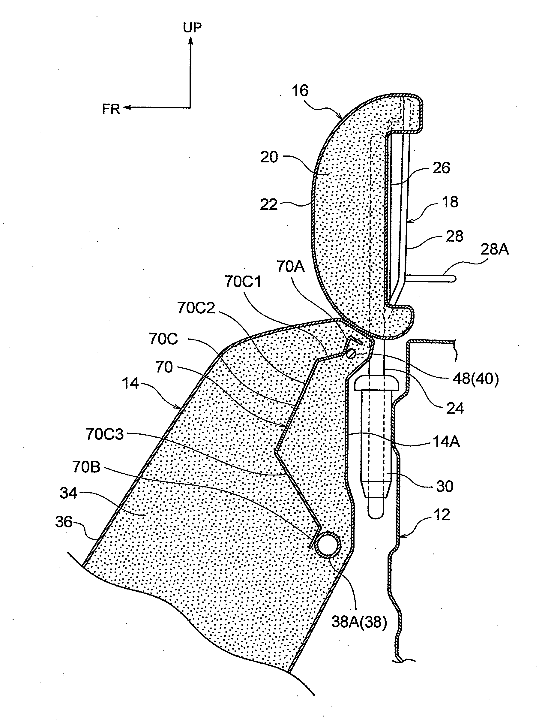
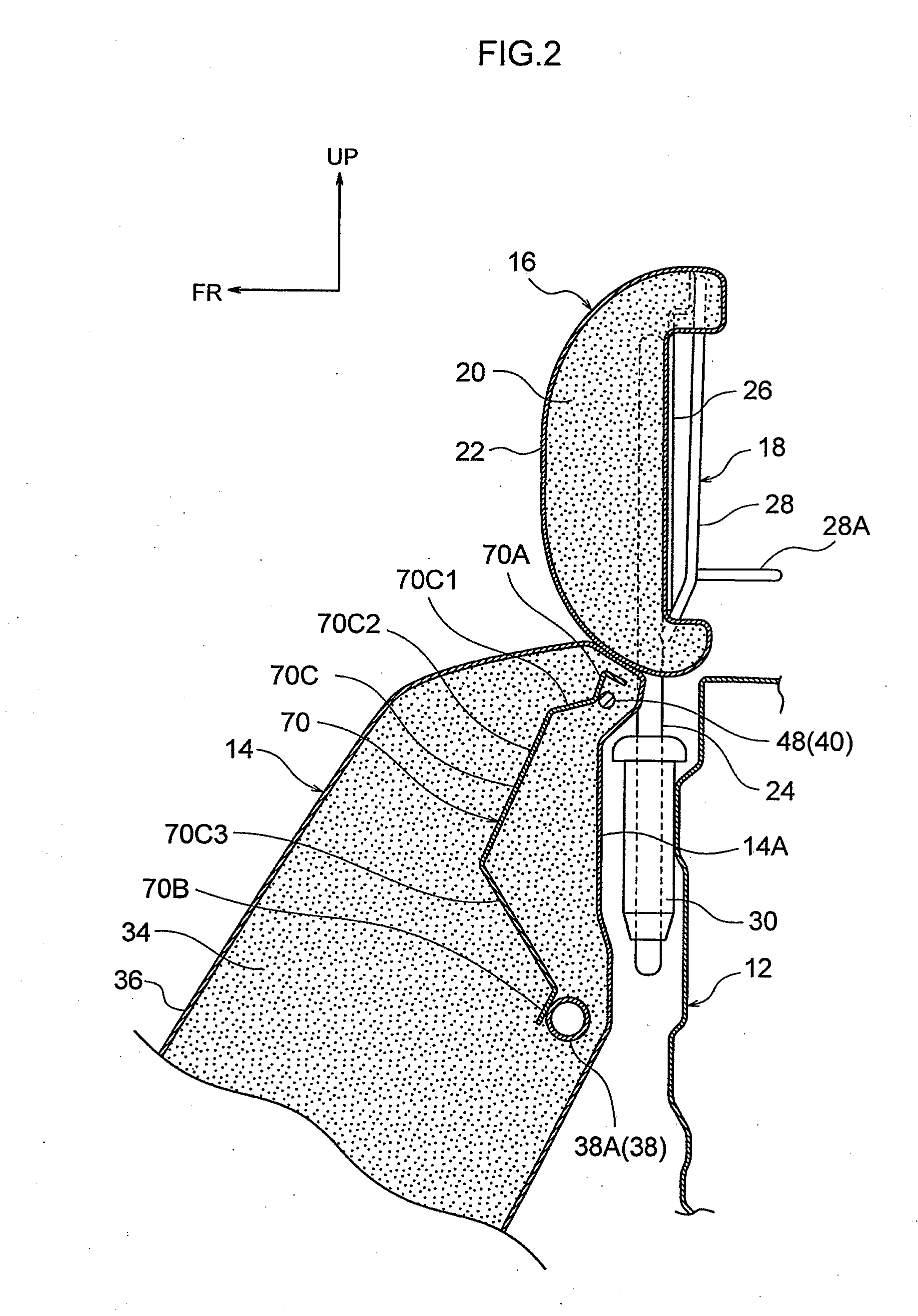
[0013]In the vehicle seat of a first aspect of the present invention a shock absorbing member is disposed at a top portion of the seatback further to the seatback front side than the headrest frame of the headrest. The shock absorbing member is attached to the seatback frame and absorbs impact energy by plastic deformation when an impact is imparted to a top portion of the seatback from the front side. Accordingly, impact energy can be efficiently absorbed by the shock absorbing member plastically deforming. Shock absorption properties can be secured even when the dimension of the shock absorbing member along the seatback thickness dimension is set small. Consequently the thickness dimension of the seatback can be set smaller.
[0037]The vehicle seat of the seventh aspect of the present invention can make the thickness dimension of the seatback even thinner.

Problems solved by technology

However, there are occasions when, due to the layout of the vehicle compartment, the seatback thickness dimension needs to be small (namely the seatback thin), and this presents problems to implementing a shock absorption structure like that described above.

Method used


Image

  • Vehicle Seat
  • Vehicle Seat
  • Vehicle Seat

Examples


Embodiment Construction

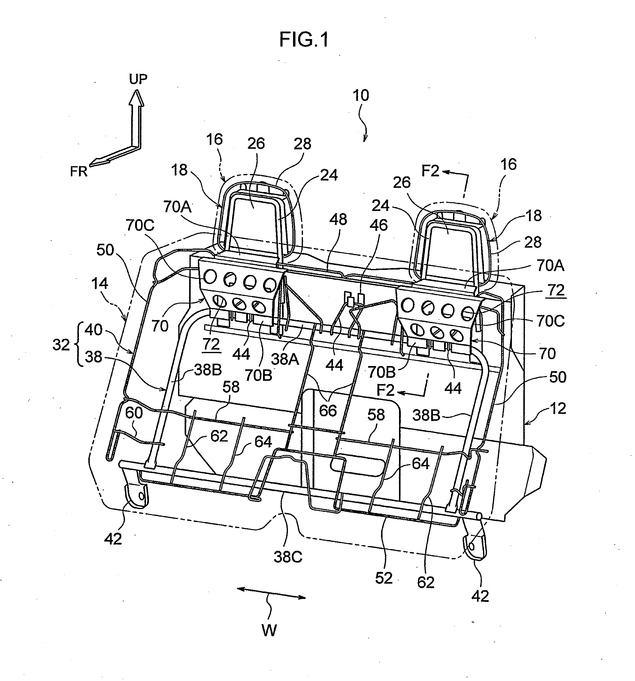
[0044]Explanation follows regarding a rear seat 10 serving as a vehicle seat according to an exemplary embodiment of the present invention with reference to FIG. 1 to FIG. 5. Arrows FR, arrows UP and arrows W in the drawings indicate the front direction, the top direction and the width direction of the rear seat 10, respectively. In the present exemplary embodiment the front direction, the top direction and the width direction of the rear seat 10 are substantially aligned with the front direction, top direction and width direction of the vehicle installed with the rear seat 10.

[0045]As shown in FIG. 1 and FIG. 2, the rear seat 10 according to the first exemplary embodiment is provided with a fixed seatback 14 disposed with a body panel 12 (vehicle body structural member) configuring the vehicle compartment behind the seatback 14. A seat cushion, not shown in the drawings, is disposed at the bottom of the seatback 14 in a configuration in which back regions of occupants seated on the...


PUM


Abstract

There is provided a vehicle seat including: a seatback including a seatback frame skeleton member covered by a seatback pad cushion member on at least a front side of the seatback frame; a headrest including a headrest frame skeleton member disposed above the seatback; and a shock absorbing member disposed further to the front side than the headrest frame and being at a top portion of the seatback, attached to the seatback frame and absorbing impact energy by plastic deformation when an impact is imparted to the top portion of the seatback from the front side.

Description

CROSS-REFERENCE TO RELATED APPLICATION[0001]This application is based on and claims priority under 35 USC 119 from Japanese Patent Application No. 2010-147976 filed on Jun. 29, 2010, the disclosure of which is incorporated by reference herein.BACKGROUND[0002]1. Technical Field[0003]The present invention relates to a vehicle seat.[0004]2. Related Art[0005]A vehicle rear seat is described in Japanese Patent Application Laid-Open (JP-A) No. 11-18871 with a seatback disposed with the vehicle body behind the seatback, and with a headrest attached to a top portion of the seatback.[0006]Such a rear seat needs to absorb impact imparted by a seated occupant, such as during impact to the rear face of the vehicle, with the headrest and the seatback. A shock absorbing structure is therefore employed, for example with a thicker seatback pad (urethane pad) and / or employing polypropylene foam having high shock absorption properties for a portion of the seatback.[0007]However, there are occasions w...

Claims


Application Information

Patent Timeline
Patent Type & Authority Applications(United States)
IPC IPC(8): B60N2/427
CPCB60N2/4228B60N2/68B60N2/48B60N2/42709B60N2/80
Inventor CYOUKYU, TAKESHINAGANO, TOMOYUKI
Owner NHK SPRING CO LTD
Learn More