

Tool with working heads and positioning unit
- Summary
- Abstract
- Description
- Claims
- Application Information
AI Technical Summary
Benefits of technology
Problems solved by technology
Method used
Image

Examples
Embodiment Construction
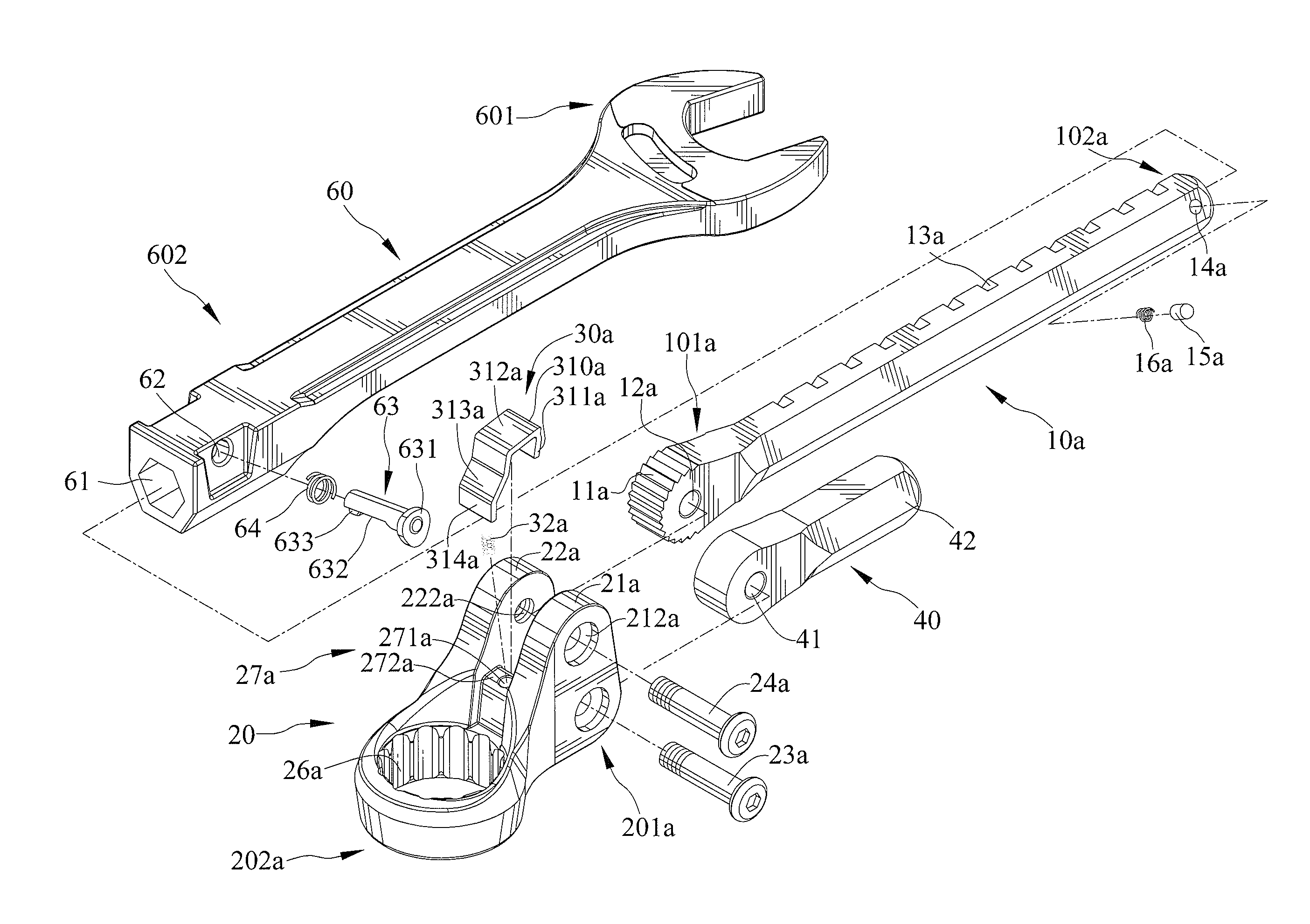
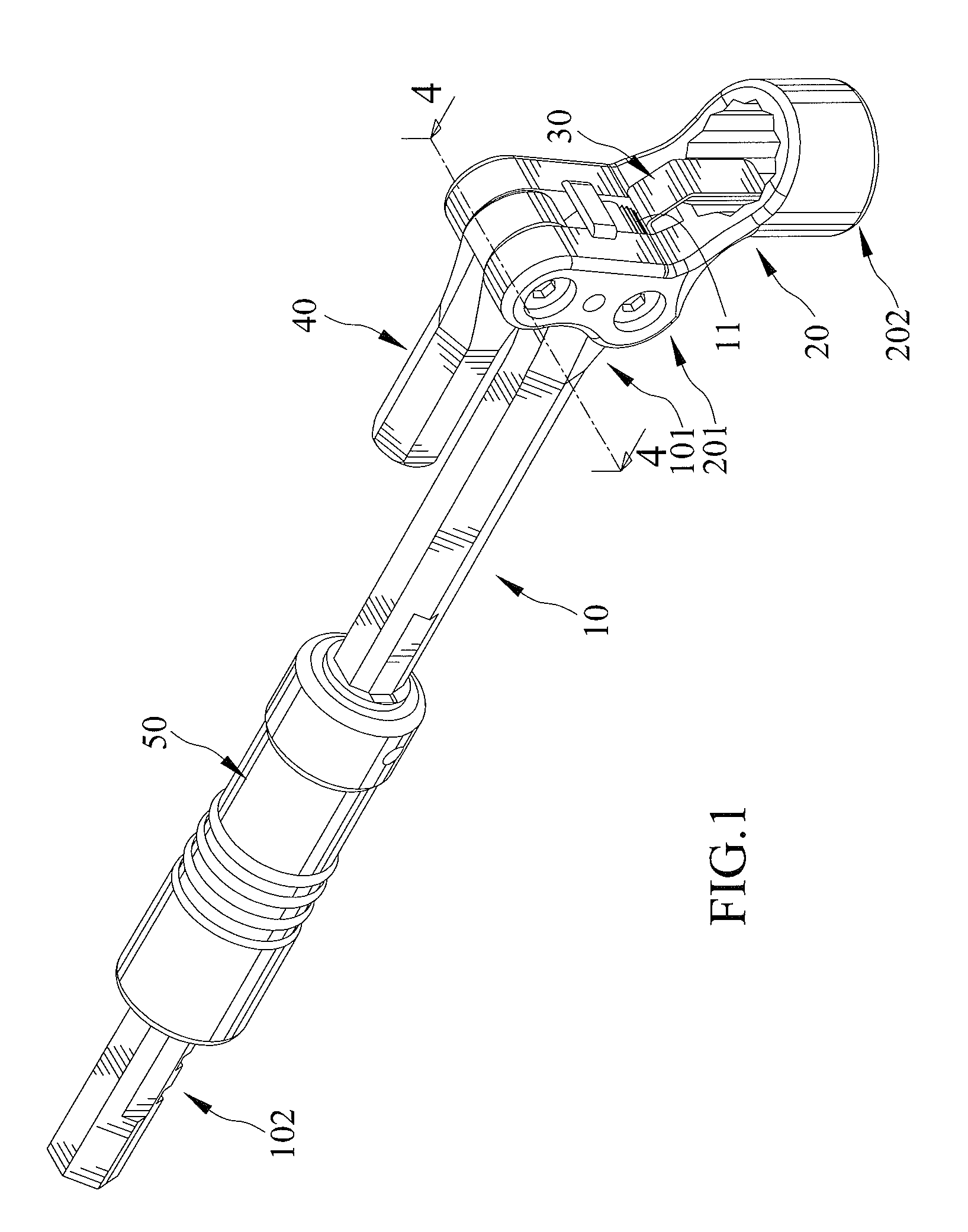
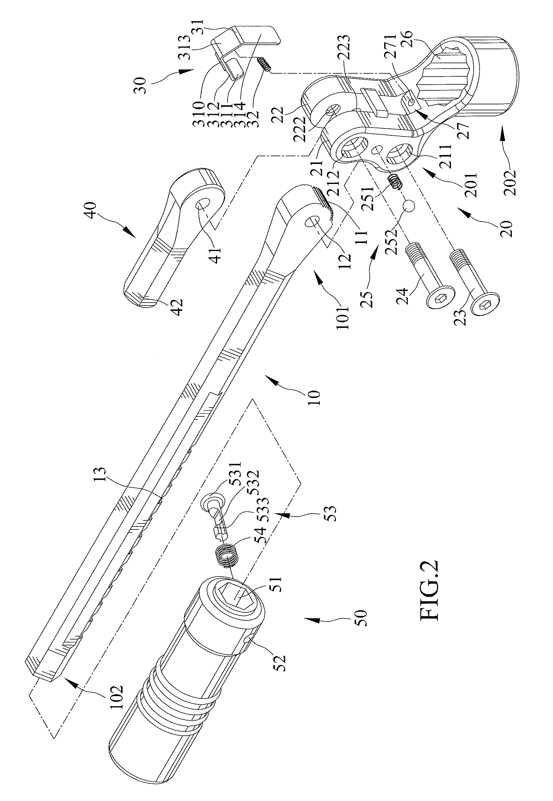
[0030]With respect to FIGS. 1 through 14, they show a tool with working heads and positioning unit in accordance with a first embodiment of the present invention. The tool includes a handle 10, which has a flat pivotal end 101 and a holding end 102 opposite to the pivotal end 101, a plurality of ratchet-like teeth 11 formed on a part of the outer periphery of the pivotal end 101. User can hold the holding end 102 to operate the tool during work. A spacing of two of intersections of the teeth 11 is small for fine-adjustment of pivotal angle between the handle 10 and a first working head 20.
[0031]The first working head 20 has a pivotal end 201 pivotally coupled to the pivotal end 101 of the handle 10 and a working end 202 adapted to engage with a work piece desired to be driven.
[0032]A positioning unit 30 is adjustable between a first position and a second position. In the first position of the positioning unit 30, the handle 10 is fixed with respect to the first working head 20; in t...
PUM
 Abstract
Description
Claims
Application Information