LED lamp strip and manufacturing process thereof

Active Publication Date: 2012-09-13
LINGSEN PRECISION INDS
View PDF8 Cites 13 Cited by
  • Summary
  • Abstract
  • Description
  • Claims
  • Application Information

AI Technical Summary

Benefits of technology

[0008]The secondary objective of the present invention is to provide a manufacturing process of the LED lamp strip, which can decrease the product cost and time.
[0009]The foregoing objective of the present invention is attained by the manufacturing process of the LED lamp strip. The manufacturing process includes the steps of providing the scrollable lead frame, forming a plurality of the through holes spaced from one another on the adhesive tape, mounting the adhesive tape to a top side of the scrollable lead frame,

Problems solved by technology

However, the high temperature resulting from the reflow process tends to bring about adve

Method used


Image

  • LED lamp strip and manufacturing process thereof
  • LED lamp strip and manufacturing process thereof
  • LED lamp strip and manufacturing process thereof

Examples


Embodiment Construction

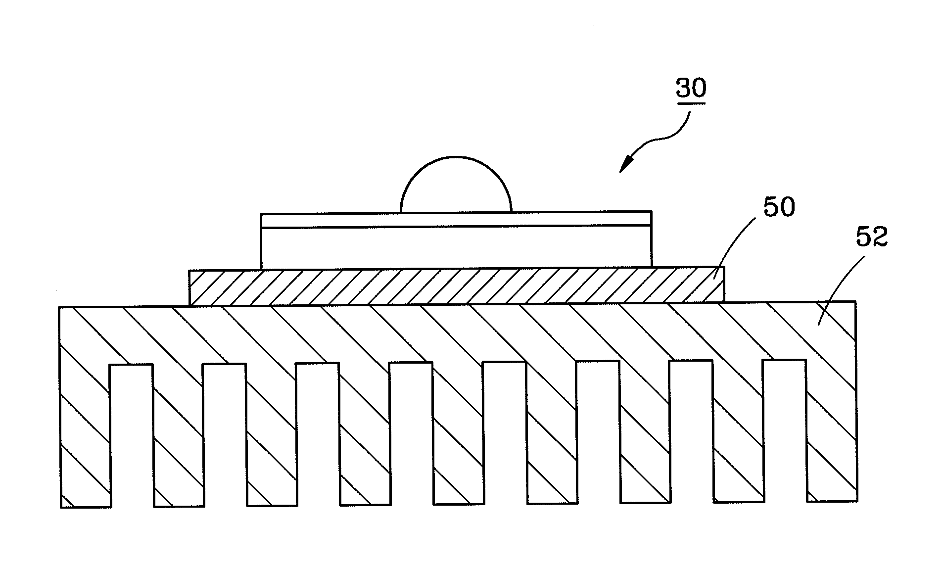
[0015]A manufacturing process of an LED lamp strip 30 in accordance with a first preferred embodiment of the present invention includes the following steps.

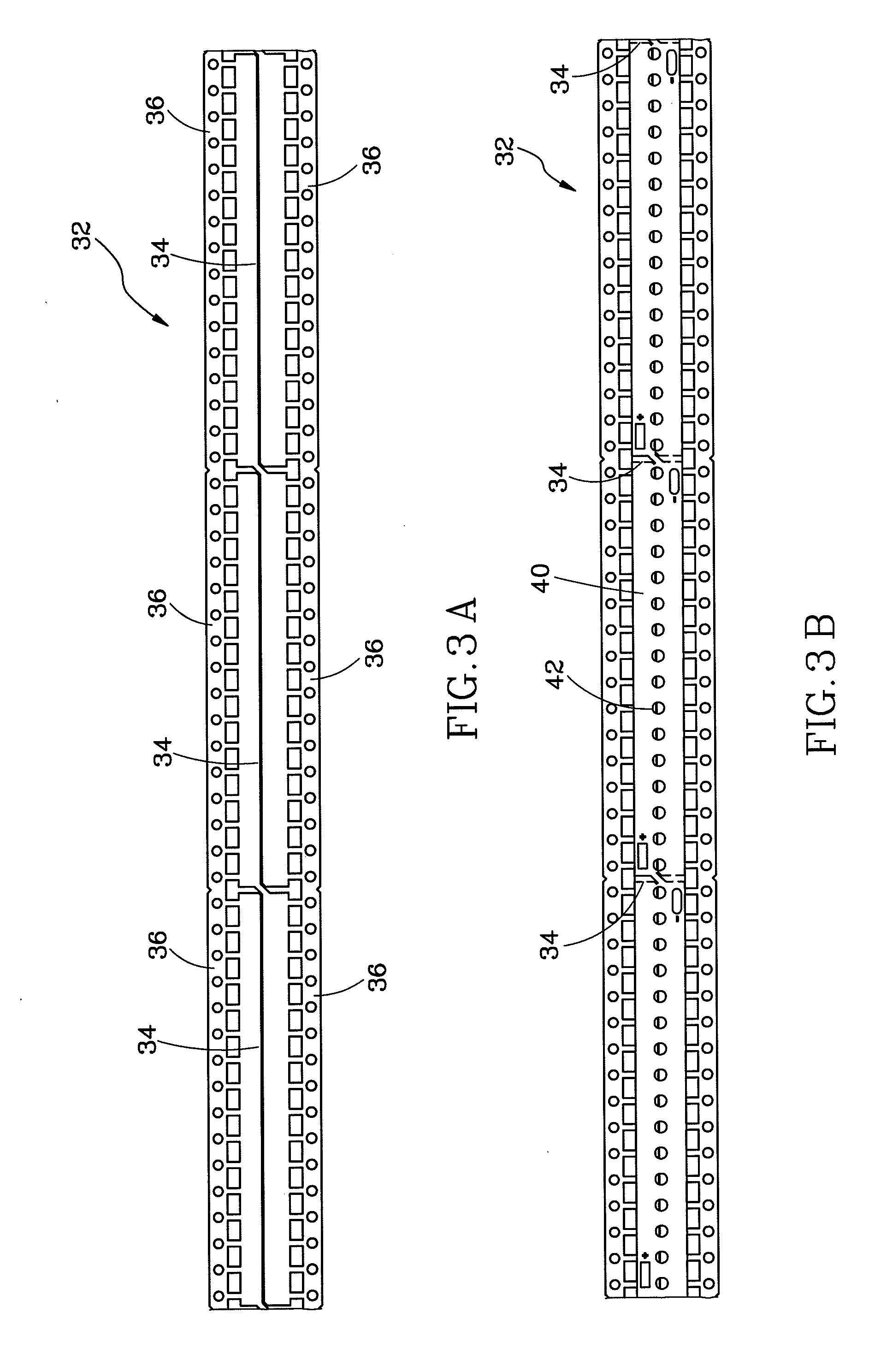
[0016]a) Provide a scrollable lead frame 32 defining a plurality of interconnected support sections 34 and a plurality of interconnected crop sections 36. As shown in FIG. 3A, a cutting line L is located between each two of the support sections 34, which are adjacent to each other. As shown in FIG. 4, each two of the crop sections 36 are connected in pair to two sides of the support section 34 separately.

[0017]b) Form a plurality of through holes 42 spaced from one another on an upper adhesive tape 40 to mark where LED chips 46 are to be adhesively mounted and where positive and negative electrodes are to be connected. And then mount the upper adhesive tape 40 to top sides of the support sections 34, as shown in FIG. 3B. Next, mount a lower adhesive tape 44 to bottom sides of the support sections 34, as shown in FIG. 3C.

[0018]c) ...


PUM


Abstract

A process of manufacturing an LED lamp strip includes the steps of forming a plurality of through holes on an adhesive tape, mounting the adhesive tape to a top side of a scrollable lead frame, bonding a plurality of LED chips to the top side of the scrollable lead frame according to the positions of the through holes, packaging the LED chips respectively, and finally cutting the scrollable lead frame. In light of this, the LED lamp strip can be produced under the circumstances of low production cost and less production time.

Description

BACKGROUND OF THE INVENTION[0001]1. Field of the Invention[0002]The present invention relates generally to an LED (light emitting diode), and more particularly, to a process of manufacturing an LED lamp strip and the LED lamp strip.[0003]2. Description of the Related Art[0004]Referring to FIG. 1, in a conventional LED lamp strip 10, a plurality of LED packages 12 are mounted on the surface of a flexible circuit board 14 by surface mounted technology (SMT) and then a reflow process is applied to the flexible circuit board 14 and the LED packages 12 to allow the LED packages 12 to be securely soldered on the surface of the flexible circuit board 14. However, the high temperature resulting from the reflow process tends to bring about adverse effect on the LED packages 12.[0005]Referring to FIG. 2, in another conventional LED lamp strip 20, a plurality of LED chips 22 are fixed on the surface of a support member 26 by an adhesive tape 24 and finally packaged separately. However, this co...

Claims


Application Information

Patent Timeline
IPC IPC(8): H01L33/62
CPCF21K9/00F21K9/90F21S4/003H01L33/62F21Y2101/02H01L2224/48091F21Y2103/003F21S4/006H01L2924/00014F21S4/20F21Y2103/10F21Y2115/10F21S4/24
Inventor TU, MING-TELIAO, MU TSAN
Owner LINGSEN PRECISION INDS
Why Eureka
Try Eureka