
Cable-Organizing Circuit Board and an Electronic Device Incorporating the Same

Active Publication Date: 2011-09-22
WISTRON CORP
View PDF9 Cites 16 Cited by
  • Summary
  • Abstract
  • Description
  • Claims
  • Application Information

AI Technical Summary

Benefits of technology

[0009]Therefore, the object of the present invention is to provide a cable-organizing circuit board that reduces the time it takes for assembling a transmission cable thereto, that maintains the tidiness and positioning stability of the transmission cable, that is relatively less costly, and that does not reduce the space available for other electronic components in an electronic device incorporating the cable-organizing circuit board in comparison with an ordinary circuit board.
[0010]Another object of the present invention is to provide an electronic device that includes a cable-organizing circuit board, that reduces the time it takes for assembling a transmission cable thereto, that maintains the tidiness and positioning stability of the transmission cable, that is relatively less costly, and that does not reduce the space available for other electronic components in the electronic device in comparison with an ordinary circuit board.
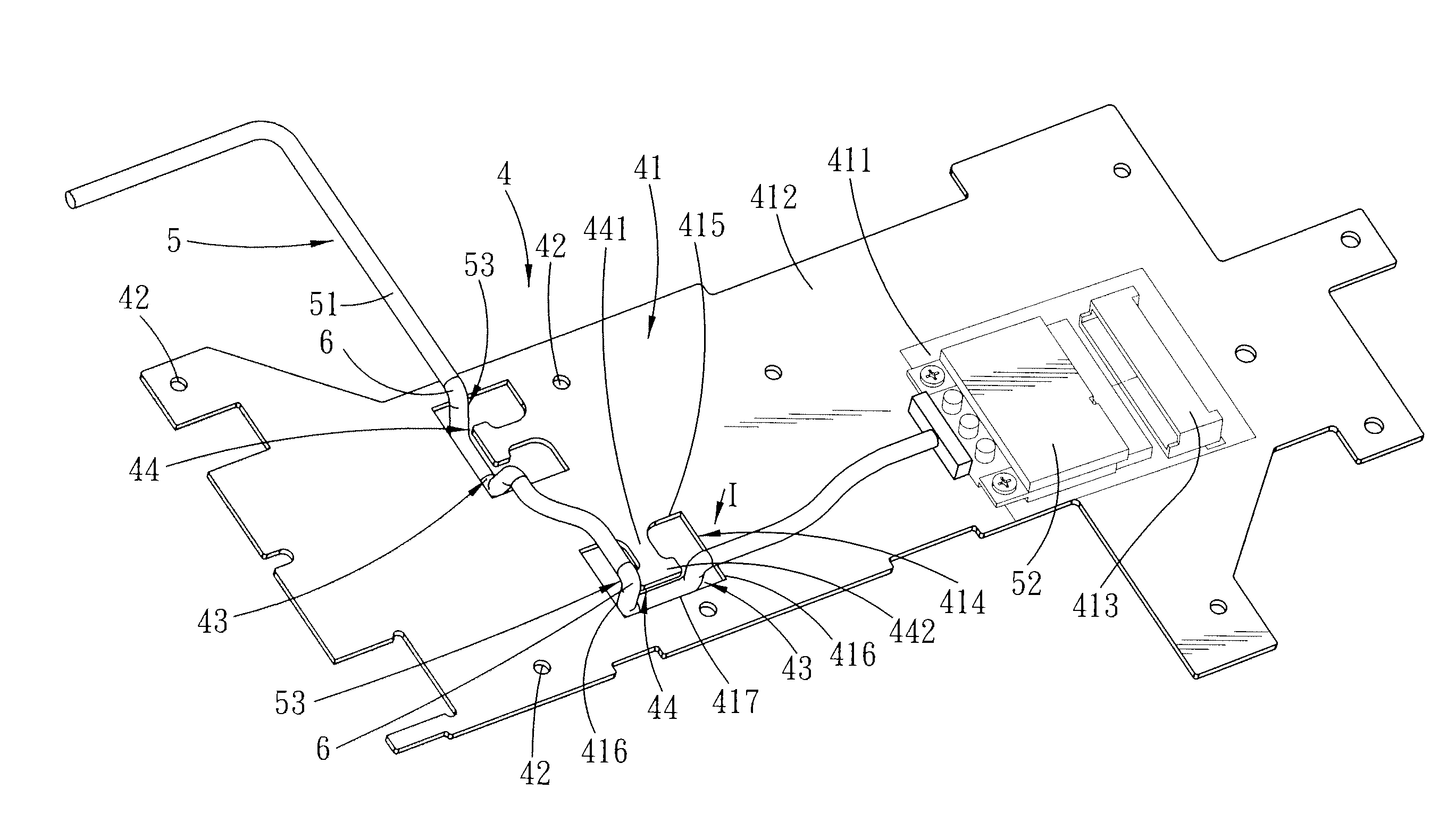
[0013]Preferably, the protruding hanger arm is co-planar with the board body. The protruding hanger arm is generally T-shaped, and includes a connecting arm portion connected to the board body, and a stop arm portion formed at a distal end of the connecting arm portion and adapted for preventing the transmission cable from slipping off the protruding hanger arm.
[0021]Preferably, the transmission cable has a bent portion that is formed with the segment of the transmission cable passing under the protruding hanger arm. In one embodiment, a distance between the third wall portion and the stop arm portion of the protruding hanger arm is not greater than an outer diameter of the transmission cable. In another embodiment, the electronic device further includes an abrasion-resistant sleeve sleeved on the bent portion of the transmission cable for contacting the protruding hanger arm. A distance between the third wall portion and the stop arm portion of the protruding hanger arm is not greater than an outer diameter of the abrasion-resistant sleeve. Accordingly, the bent portion of the transmission cable may be prevented from slipping off the protruding hanger arm.
[0022]With the features described above, the electronic device incorporating the cable-organizing circuit board according to the present invention has the following effects and advantages. Through the design of the protruding hanger arm of the cable-organizing circuit board and the optional design of the through hole, the transmission cable can be directly passed beneath the protruding hanger arm, or be quickly extended through the through hole and passed beneath the protruding hanger arm, such that the transmission cable is neatly and stably positioned on the cable-organizing circuit board. As such, the time and production cost for cable organization is reduced, and the space available for other electronic components of the electronic device is not undesirably reduce in comparison with an ordinary circuit board.

Problems solved by technology

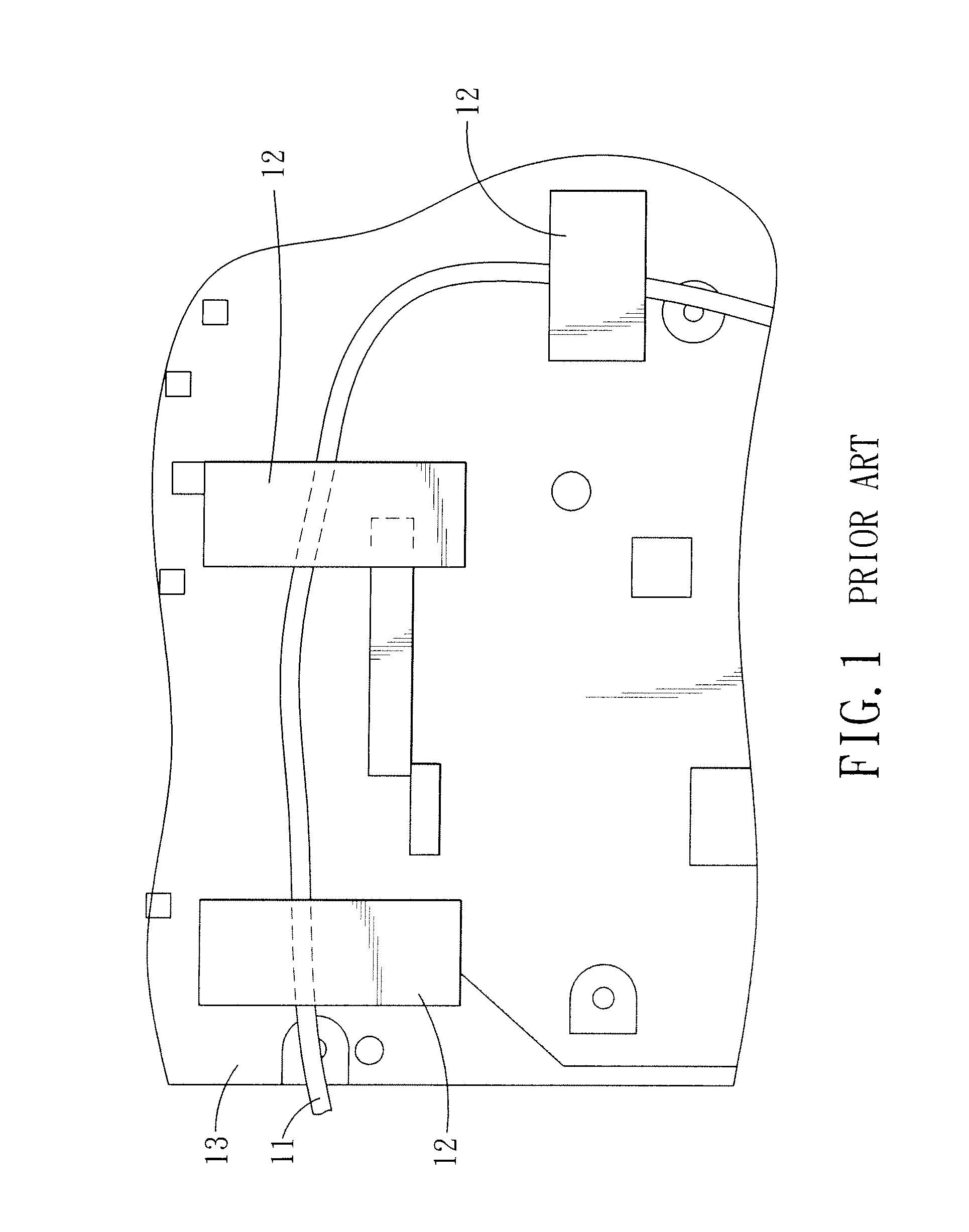
However, one disadvantage of this method is that the adhesiveness of the adhesive tape segments 12 is material dependent, and may deteriorate due to an increase in operating temperature of electronic components on the circuit board 13 or inside the housing.
Therefore, the adhesive tape segments 12 may easily fall off, resulting in unstable positioning of the transmission cable 11 on the circuit board 13 or on the housing.
Moreover, this method is time-consuming, and the use of the adhesive tape segments 12 increases cost.
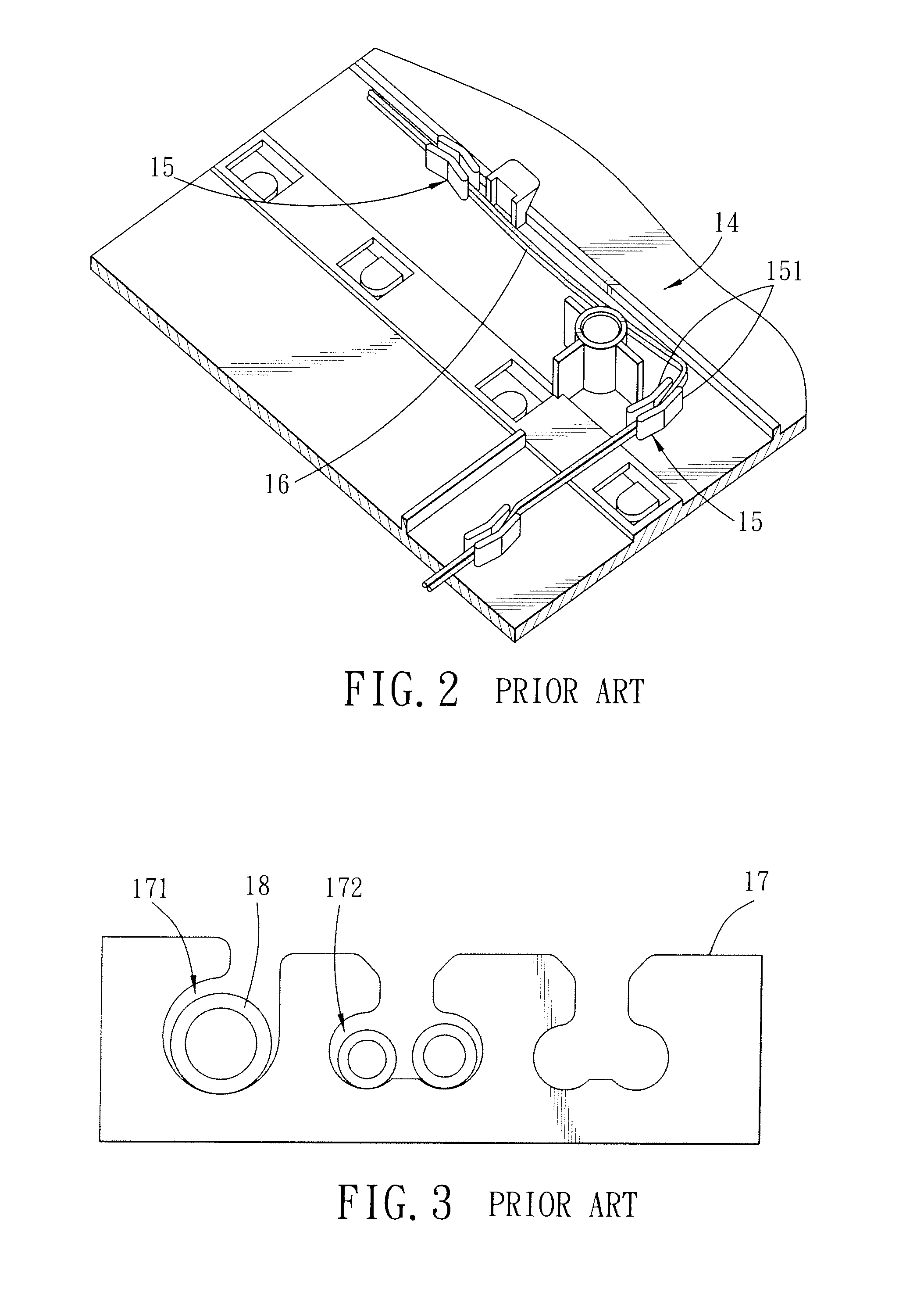
This kind of cable-organizing method requires the developing of an additional mold for production of the cable-organizing board 17, thereby increasing the production cost for an electronic device (e.g., a notebook computer) incorporating the same.

Method used


Image

  • Cable-Organizing Circuit Board and an Electronic Device Incorporating the Same
  • Cable-Organizing Circuit Board and an Electronic Device Incorporating the Same
  • Cable-Organizing Circuit Board and an Electronic Device Incorporating the Same

Examples


Embodiment Construction

[0033]Before the present invention is described in greater detail, it should be noted that like elements are denoted by the same reference numerals throughout the disclosure.

[0034]With reference to FIG. 4, the first embodiment of an electronic device 200 incorporating a cable-organizing circuit board 4 according to the present invention is shown. The electronic device 200 includes a housing 2, a display screen 3 pivoted to a rear side of the housing 2, a cable-organizing circuit board 4, and a transmission cable 5. In this embodiment, the electronic device 200 is illustrated as a notebook computer. However, it is noted herein that, in practice, the electronic device 200 may be a cellular phone, a personal digital assistant (PDA), a server, a tablet computer, etc.

[0035]As shown in FIG. 4 and FIG. 5, the housing 2 forms a receiving space 21 for receiving the cable-organizing circuit board 4 and the transmission cable 5 therein. The cable-organizing circuit board 4 includes a board bod...


PUM


Abstract

A cable-organizing circuit board includes a board body and a protruding hanger arm. The board body has a circuit-layout section and a non-circuit-layout section that are connected to each other. The protruding hanger arm is disposed at the non-circuit-layout section of the board body, and is adapted to be permit a segment of the transmission cable to pass thereunder. The segment of the transmission cable is disposed beneath a bottom surface of the protruding hanger arm, and remaining segments of the transmission cable are disposed above a top surface of the board body opposite to the bottom surface of the protruding hanger arm when the segment of the transmission cable passes under the protruding hanger arm.

Description

CROSS-REFERENCE TO RELATED APPLICATION[0001]This application claims priority of Taiwanese Application No. 099204759, filed on Mar. 18, 2010.BACKGROUND OF THE INVENTION[0002]1. Field of the Invention[0003]The invention relates to a cable-organizing circuit board and an electronic device including the cable-organizing circuit board, more particularly to a cable-organizing circuit board that is provided with a protruding hanger arm for facilitating organization of a transmission cable and to an electronic device incorporating the cable-organizing circuit board.[0004]2. Description of the Related Art[0005]During assembly of notebook computers, cable organization is an important step. Conventional cable-organizing methods include the following:[0006]As shown in FIG. 1, after a transmission cable 11 is arranged in a predefined route, several adhesive tape segments 12 are used to adhere the transmission cable 11 to a circuit board 13 or to a housing (not shown). However, one disadvantage o...

Claims


Application Information

Patent Timeline
IPC IPC(8): H05K5/00H05K1/00
CPCG06F1/183G06F1/184G06F1/189H05K2201/10356H05K2201/09081H05K2201/09145H05K1/02H01R4/64H02G3/0666
Inventor HUANG, CHIH-PINGLAI, KUN-HUICHUANG, CHENG-HSIANG
Owner WISTRON CORP
Learn More