
Magnetised structure inducing a homogeneous field, in the centre thereof, with a pre-determined orientation

a magnetised structure and homogeneous field technology, applied in the field of magnetized structure, can solve the problems of bulky devices and difficult to move, limited remanence of so-called permanent materials, and difficult to mov

Inactive Publication Date: 2012-01-19
COMMISSARIAT A LENERGIE ATOMIQUE ET AUX ENERGIES ALTERNATIVES
View PDF8 Cites 29 Cited by
  • Summary
  • Abstract
  • Description
  • Claims
  • Application Information

AI Technical Summary

Benefits of technology

[0022]Generally speaking, the present invention aims to make it possible to produce a magnetized structure inducing at its center an arbitrarily homogeneous field having a direction that may vary over the range 0 degrees (°) to 90° relative to the longitudinal axis of the structure.
[0026]Contiguous sectors make it possible to have the best possible filling with magnetic material whereas non-contiguous sectors offer the possibility of fine adjustment.

Problems solved by technology

Because of this, the devices are bulky and difficult to move.
Resistive windings require high-current feeds, while superconducting windings imply the use of a cryostat filled with cryogenic liquids, which is difficult to move.
Moreover, so-called permanent materials are limited in terms of remanence (the magnetization remaining in the material once magnetized) and generating high fields in large areas of use requires large quantities of material.
Since the density of these materials is approximately 7.5 g·cm3, these systems quickly become very heavy.
The difficulty with magnetic systems using permanent materials for NMR lies in the requirement to combine intense fields with high homogeneity.
The methods of producing materials such as NdFeB cannot guarantee perfect homogeneity of magnetization or perfect repetitivity.
This is because the NMR applications that require high homogeneity also require the devices to be either very large (in MRI where a human body must be placed inside the device), which implies an enormous quantity of material (several tons), or very intense (in NMR spectroscopy, which uses fields exceeding 10 teslas (T), at present up to 20 T), which is simply not feasible at present with permanent materials.
Moreover, the proposed structure is not simple to manufacture.
These two conditions cannot be achieved in practice.
With a human being in particular, it is inconceivable to rotate a person in the device.
There is at present no proposal for generating a homogeneous field at an arbitrary angle only from magnetized parts, especially since manipulating magnetized parts to assemble them proves difficult given all the forces linked to the magnetism of the parts, which may be extremely intense when assembling large parts.

Method used


Image

  • Magnetised structure inducing a homogeneous field, in the centre thereof, with a pre-determined orientation
  • Magnetised structure inducing a homogeneous field, in the centre thereof, with a pre-determined orientation
  • Magnetised structure inducing a homogeneous field, in the centre thereof, with a pre-determined orientation

Examples


Embodiment Construction

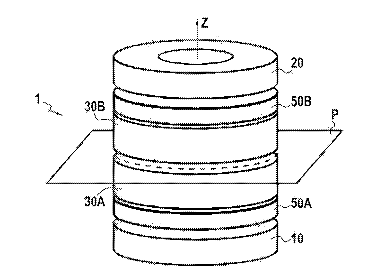
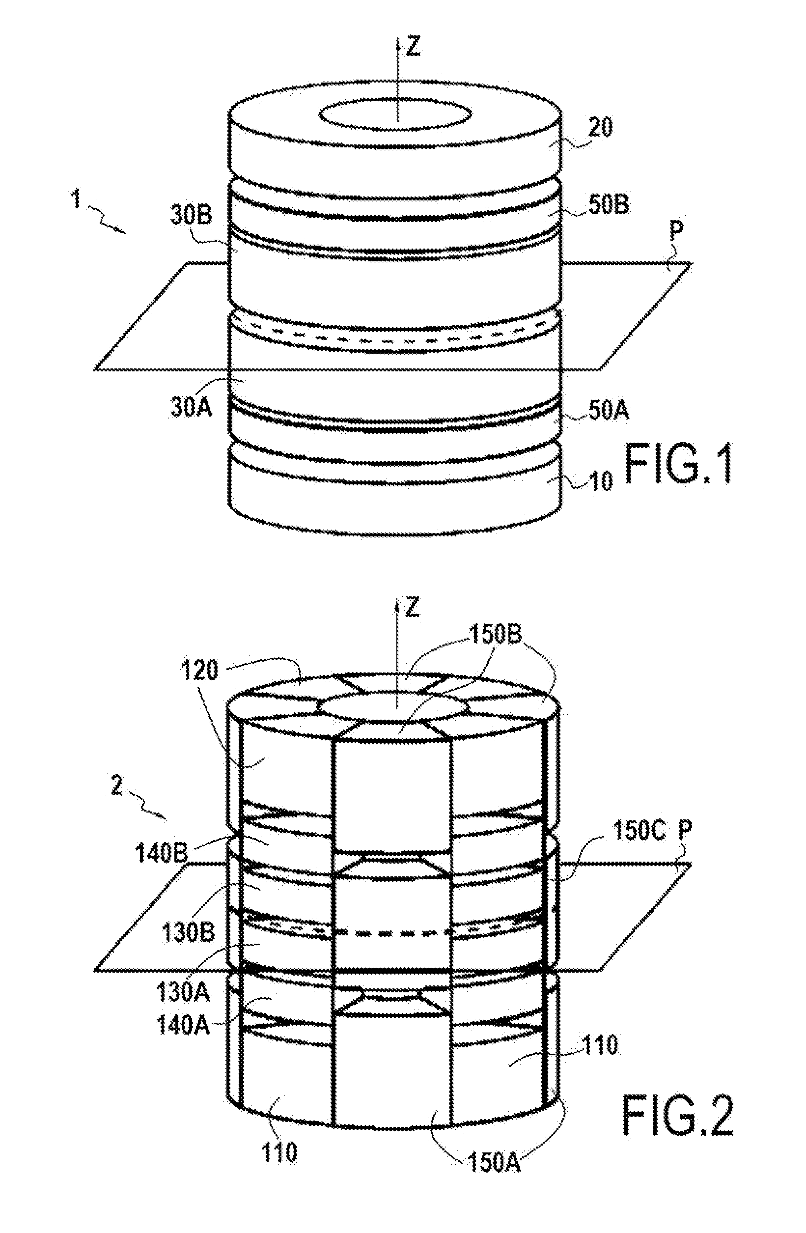
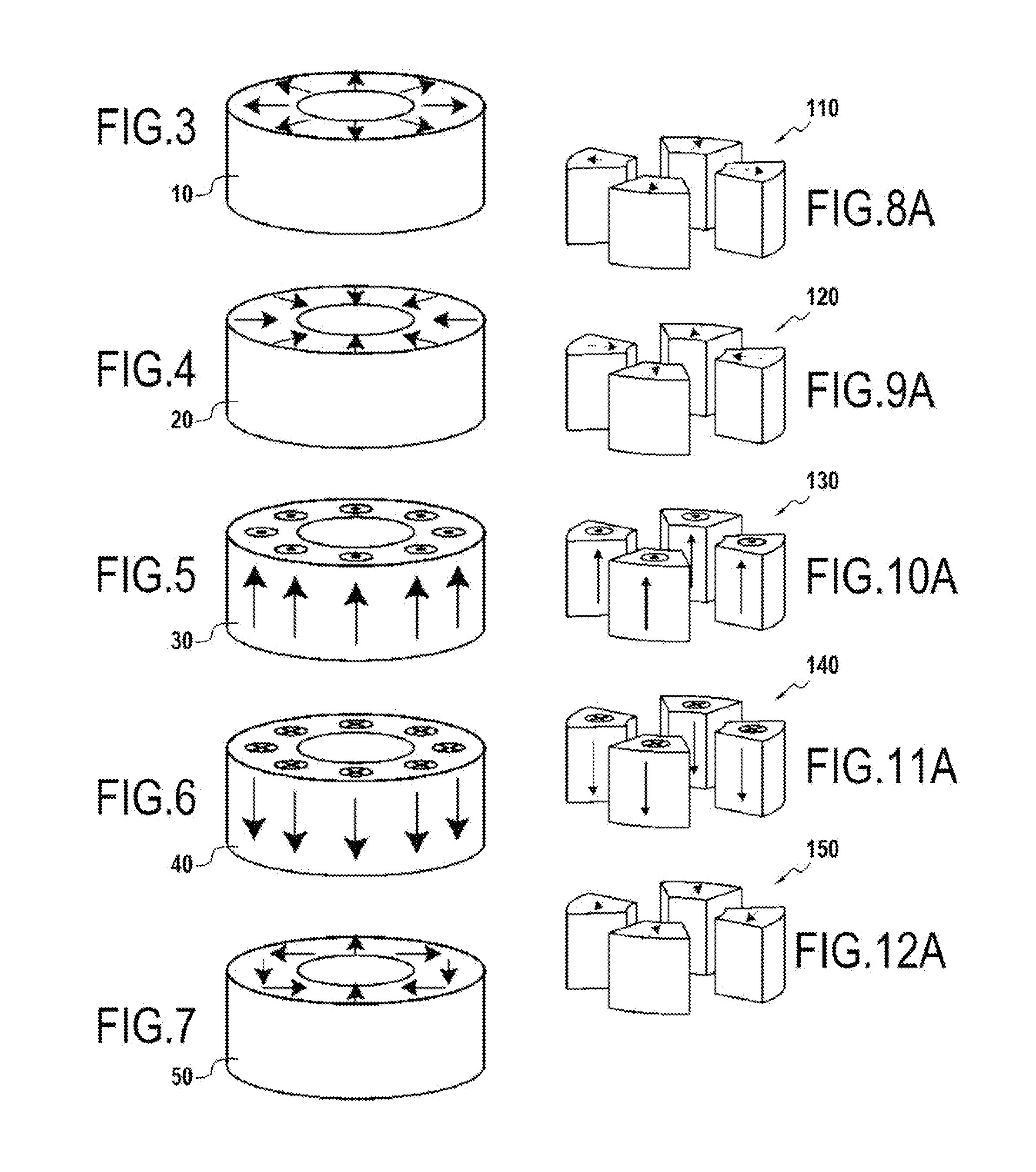
[0059]Generally speaking, the present invention relates to a way of assembling magnetized parts in order to create a homogeneous and intense magnetic field at the center of a structure. The field induced at the center may have an arbitrary orientation relative to the axis of the structure. The orientation and homogeneity of the field are controlled by the number, disposition, and dimensions of the components subject to certain general rules that are discussed below. Such a structure is of particular benefit for NMR and MRI and in particular makes it possible to create a field pointing essentially at the so-called “magic” angle (arctan θm=√{square root over (2)}) to the axis of the magnetized structure.

[0060]The present invention makes it possible to produce a family of essentially cylindrical permanent magnets that produce an arbitrarily homogeneous magnetic field having a direction relative to the axis of the cylinder that may vary over the range 0° to 90°.

[0061]The general structu...


PUM


Abstract

A magnetized structure that induces in a central area of interest a homogeneous magnetic field of predetermined orientation relative to a longitudinal axis (z) of the structure comprises at least two magnetized rings (110, 120) disposed symmetrically relative to a plane (P) that is perpendicular to the longitudinal axis (z) and that contains the central area of interest, and at least one median annular magnetized structure disposed at least partly between the two magnetized rings (110, 120) and also disposed symmetrically relative to the plane (P) of symmetry, one of the two magnetized rings (110) being magnetized radially relative to the longitudinal axis (z) with divergent magnetization and the other of the two magnetized rings (120) being magnetized radially relative to the longitudinal axis (z) with convergent magnetization, and the median annular magnetized structure being magnetized with an orientation different from that of the magnetization of the two magnetized rings (110, 120). The median annular magnetized structure comprises at least one magnetized ring (150) having a magnetization distribution of orientation that varies as in Halbach dipoles and the first two magnetized rings (110, 120) and the median annular magnetized structure are each divided into individual components in the form of regularly distributed identical sectors.

Description

FIELD OF THE INVENTION[0001]The present invention relates to a magnetized structure applied to a nuclear magnetic resonance device that induces in a central area of interest a homogeneous magnetic field of predetermined orientation relative to a longitudinal axis of the structure, the structure comprising at least first and second magnetized rings disposed symmetrically relative to a plane that is perpendicular to said longitudinal axis and that contains said central area of interest and at least one median annular magnetized structure disposed at least partly between the first and second magnetized rings and also disposed symmetrically relative to said plane, the first magnetized ring being magnetized radially relative to the longitudinal axis with divergent magnetization, the second magnetized ring being magnetized radially relative to the longitudinal axis with convergent magnetization, and the median annular magnetized structure being magnetized with an orientation different fro...

Claims


Application Information

Patent Timeline
Patent Type & Authority Applications(United States)
IPC IPC(8): G01R33/44
CPCG01R33/307H01F7/0278G01R33/383
Inventor SAKELLARIOU, DIMITRIOSHUGON, CEDRICAUBERT, GUY
Owner COMMISSARIAT A LENERGIE ATOMIQUE ET AUX ENERGIES ALTERNATIVES
Learn More