Uniform microwave heating method and apparatus

a microwave heating and uniform technology, applied in microwave heating, electrical/magnetic/electromagnetic heating, electrical apparatus, etc., can solve the problems of non-uniform heating, many applications do not allow the inclusion of such materials, and limit the space available in the cavity for the target material, so as to promote uniform heating

Inactive Publication Date: 2006-05-18
HRL LAB
View PDF4 Cites 19 Cited by
  • Summary
  • Abstract
  • Description
  • Claims
  • Application Information

AI Technical Summary

Benefits of technology

[0020] In accordance with the present invention a method is provided for creating uniform heating of an absorptive target, and, is particularly useful for heating a large-area slab-like or substrate absorptive target.
[0021] In one aspect of the invention a circularly polarized waveguide mode is created that will promote uniform heating by rotating a propagated non-uniform field pattern around a central axis of a cylindrical cavity or waveguide. In the process of rotating the field pattern, hot and cold spots in the field pattern are averaged out over time. Exemplary embodiments of the present invention operate with a single high-power (>1 kW) source, such that multiple power sources are not required as in other state-of-the-art methods. Multiple microwave power feeds are introduced into the system, each one with a fixed phase shift from the other.
[0022] In one aspect providing uniform microwave heating of a microwave absorptive target in accordance with the present invention, a microwave housing having a longitudinal axis is sized to propagate a selected waveguide mode at an operating frequency. The microwave absorptive target is located in an axial cross-sectional area of the microwave housing relative to the longitudinal axis. Microwave energy at the operating frequency is applied into the microwave housing to propagate a circularly polarized waveguide mode in the microwave housing to time average azimuthal field strength across the axial cross-sectional area. The applied microwave energy may be split into a first signal and a second signal ninety degrees out of phase with the first signal. The first signal and the second signal may be applied into the microwave housing at ninety angular degrees apart azimuthally relative to the longitudinal axis to provide the first signal and the second signal into the microwave housing as respective orthogonal components of an applied field strength. The

Problems solved by technology

The use of microwave radiation is a well known method for heating substances that have intrinsic absorption properties, but it is often difficult to remove the effects of cavity and waveguide modes that lead to non-uniform heating and “hot spots” in the target to be heated.
The disadvantage is that many applications do not allow the inclusion of such material within the processing environment.
Another disadvantage is that the loading material limits the space available within the cavity for the target.
However, the waveguide structures are complicated multiple-layer structures that must be fabricated within the microwave structure.
In many cases, the added complexity is undesirable, such as, for example, a conveyer belt system moving over microwave emitting slots in a waveguide.
This methodology relies on the disadvantage imposed by fixed-frequency microwave heating cavities that are known to have cold spots and hot spots.
With a relatively low frequency microwave introduced into a small cavity, standing waves occur and, thus, the microwave power does not uniformly fill all of the space within the cavity, and the unaffected regions are not heated.
However, a frequency of 28 GHz is considered to be prohibitively expensive for commercial use.
However, in many cases, the increased comp

Method used


Image

  • Uniform microwave heating method and apparatus
  • Uniform microwave heating method and apparatus
  • Uniform microwave heating method and apparatus

Examples


Embodiment Construction

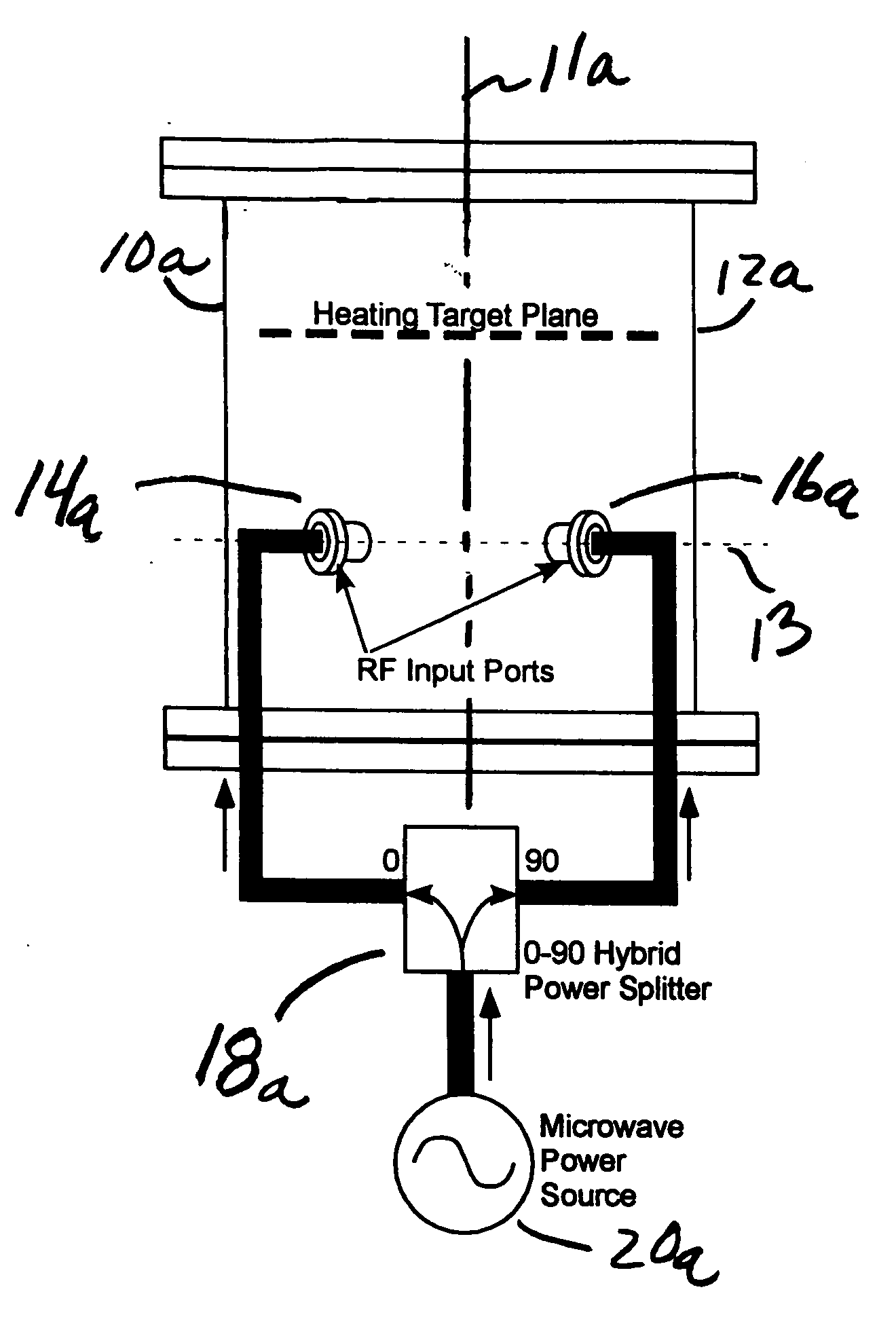
[0030] When using microwaves to heat various materials for various purposes, one usually has to live with an inherent non-uniformity in the heating of the target material, due to electromagnetic modes that constrain the heating energy to specific patterns within the heating cavity. Considering that the cavity typically consists of a cylindrical geometry of arbitrary cross section, the most common being rectangular or circular. Microwave radiation is introduced into the cavity at a coupler port designed for that purpose. The electromagnetic radiation within the cavity is distributed among several orthonormal cavity modes. Each mode is a solution to the Maxwell's wave equation given the cavity's particular boundary conditions.

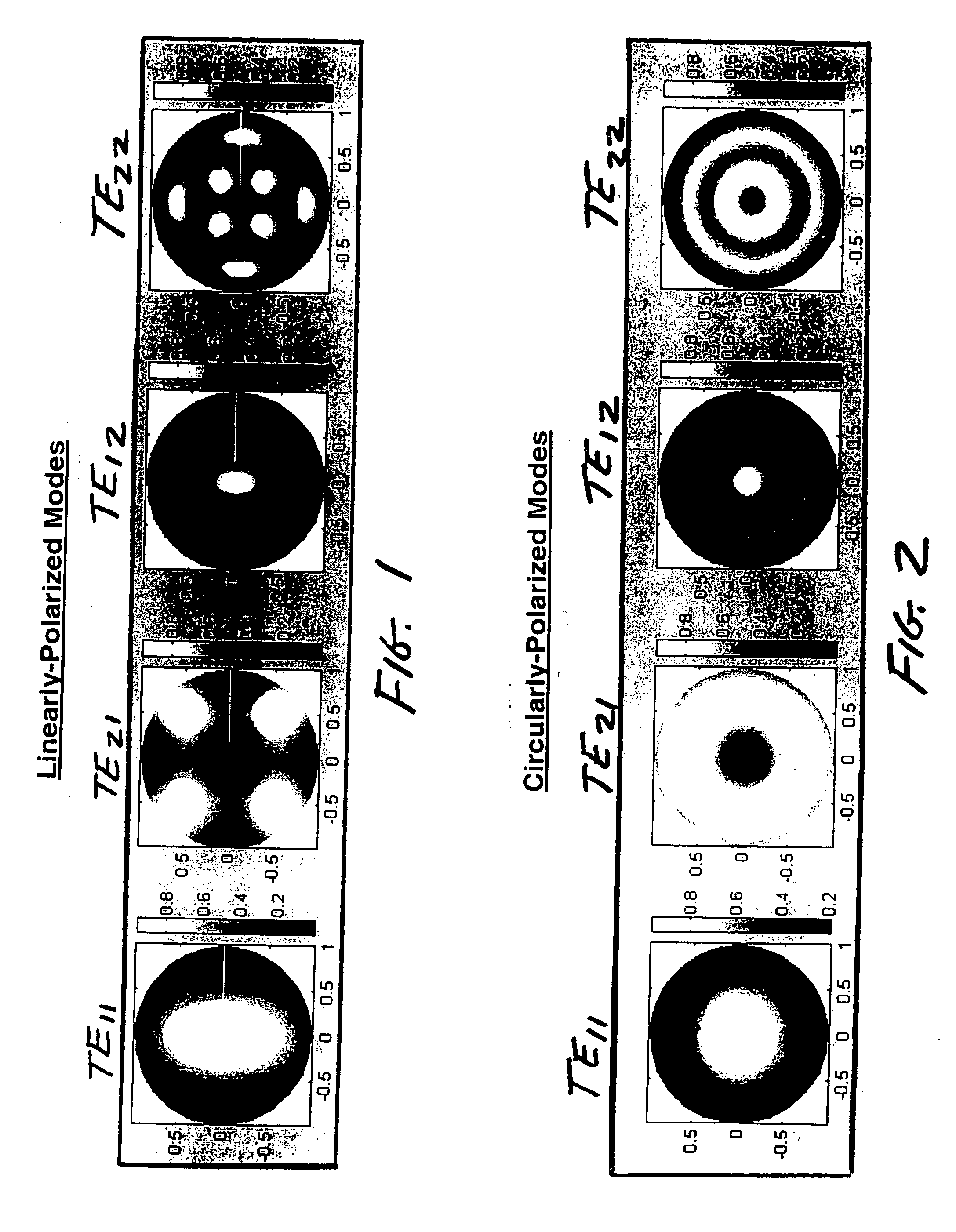
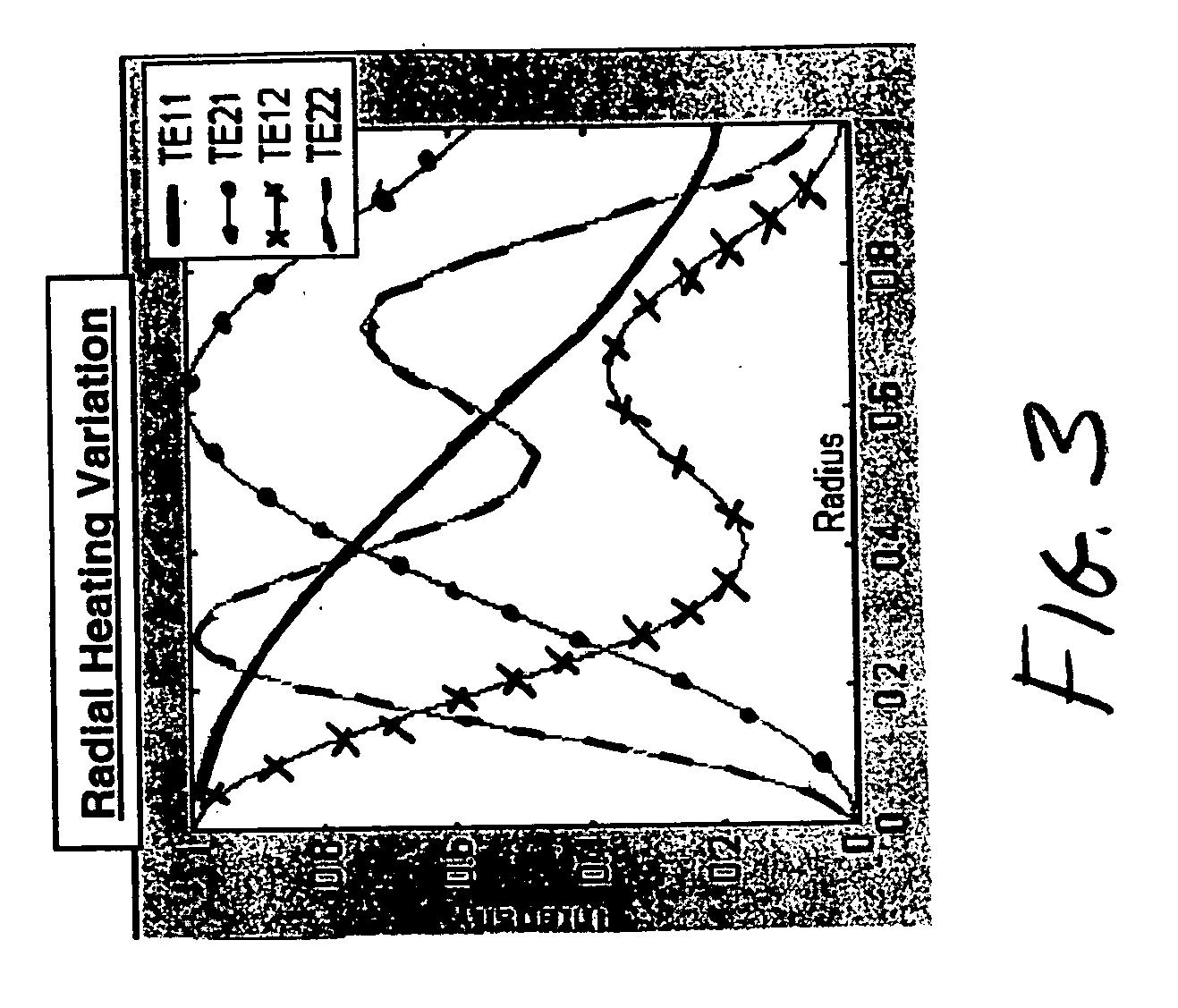
[0031]FIG. 1 illustrates the heating pattern intensity as a function of radius that would be experienced by targets placed across the cross section of a right circular cylindrical cavity (or waveguide) with conductive walls and tuned to support various linearly ...


PUM


Abstract

A method and apparatus for creating uniform heating of an microwave absorptive target. A circularly polarized waveguide mode is created that promotes uniform heating of the microwave absorptive target by rotating a propagated non-uniform field pattern around a central axis of a cylindrical cavity or waveguide. In the process of rotating the field pattern, hot and cold spots in the field pattern are averaged out over time.

Description

BACKGROUND OF THE INVENTION [0001] 1. Field of the Invention [0002] The present invention relates to the field of heating, and more particularly, to the use of microwave radiation for heating slab-like layers or surfaces. [0003] 2. Description of the Related Art [0004] The use of microwave radiation is a well known method for heating substances that have intrinsic absorption properties, but it is often difficult to remove the effects of cavity and waveguide modes that lead to non-uniform heating and “hot spots” in the target to be heated. [0005] Many processes also require uniform heating and a method of applying heat energy noninvasively. For example, the use of microwave heating has been proven to be effective for the processing of dielectric material. In many cases, a uniform temperature distribution within the product is required. [0006] There have been many proposals that use a TEM waveguide mode to create a uniform field distribution. A waveguide or cavity is loaded with high ...

Claims


Application Information

Patent Timeline
IPC IPC(8): H05B6/70
CPCH05B6/70H05B6/704
Inventor GREGOIRE, DANIELCOLBURN, JOSEPH
Owner HRL LAB
Why Eureka
Try Eureka