Dual conveyor jet impingement oven

a conveyor and oven technology, applied in the field of ovens for cooking foods, can solve the problems of low baking speed of certain foods, limited kitchen space available in fast food restaurants for conveyor ovens, and exchange of internal hot air with room air, so as to increase the speed at which foods can be cooked, reduce heat loss, and reduce heat loss.

Inactive Publication Date: 2005-04-19
GAS TECH INST
View PDF10 Cites 69 Cited by
  • Summary
  • Abstract
  • Description
  • Claims
  • Application Information

AI Technical Summary

Benefits of technology

[0006]Accordingly, it is one object of this invention to provide an impingement heating apparatus which reduces heat losses occurring as the result of the exchange of heated air from within the heating space or chamber with room air compared to conventional conveyor ovens.
[0007]It is another object of this invention to provide an impingement heating apparatus which provides higher heat transfer rates over conventional impingement heating equipment, thereby increasing the speed at which the foods can be cooked.
[0008]It is yet a further object of this invention to provide an impingement heating apparatus which provides for more uniform heating and greater efficiency than conventional ovens so as to increase the food output per unit of kitchen space occupied by the apparatus.
[0009]These and other objects of this invention are addressed by a heating apparatus comprising at least one wall enclosing a blower box and forming at least one air inlet opening and at least two air outlet openings and at least one heating section wall defining a heating space adjacent to and in fluid communication with the blower box. Two spaced apart pairs of spaced apart heated air distribution plenums are disposed within the heating space and form a return air conduit therebetween, which return air conduit has a return outlet end in fluid communication with the at least one air inlet opening of the blower box. Each of the spaced apart heated air distribution plenums includes a heated air inlet opening in fluid communication with the at least two air outlet openings. A horizontal heating surface is disposed between each pair of spaced apart heated air distribution plenums and each of the heated air distribution plenums comprises a substantially horizontally disposed, perforated heated air distribution plate facing the horizontal heating surface. The horizontal heating surface is typically a porous conveyor for conveying items to be heated, such as food, whereby the heated air streams ejected from the lower of the spaced apart heated air distribution plenums directly impinge onto the bottom surface thereof. Incorporated into the heated air distribution plates is a novel jet nozzle design whereby the air streams ejected from the heated air distribution plenums vertically impinge upon the food surface and porous conveyor, which design reduces the exchange of internal heated air with room air, thereby increasing oven uniformity and efficiency.

Problems solved by technology

A major problem associated with conveyor ovens is the exchange of internal hot air with room air due to losses from the conveyor tunnel / heating space.
A further problem is the low speed of baking certain foods due to low heat transfer.
Yet a further problem is the limited kitchen space available in fast food restaurants for conveyor ovens capable of meeting the peak demands of their customers.

Method used


Image

  • Dual conveyor jet impingement oven
  • Dual conveyor jet impingement oven
  • Dual conveyor jet impingement oven

Examples


Embodiment Construction

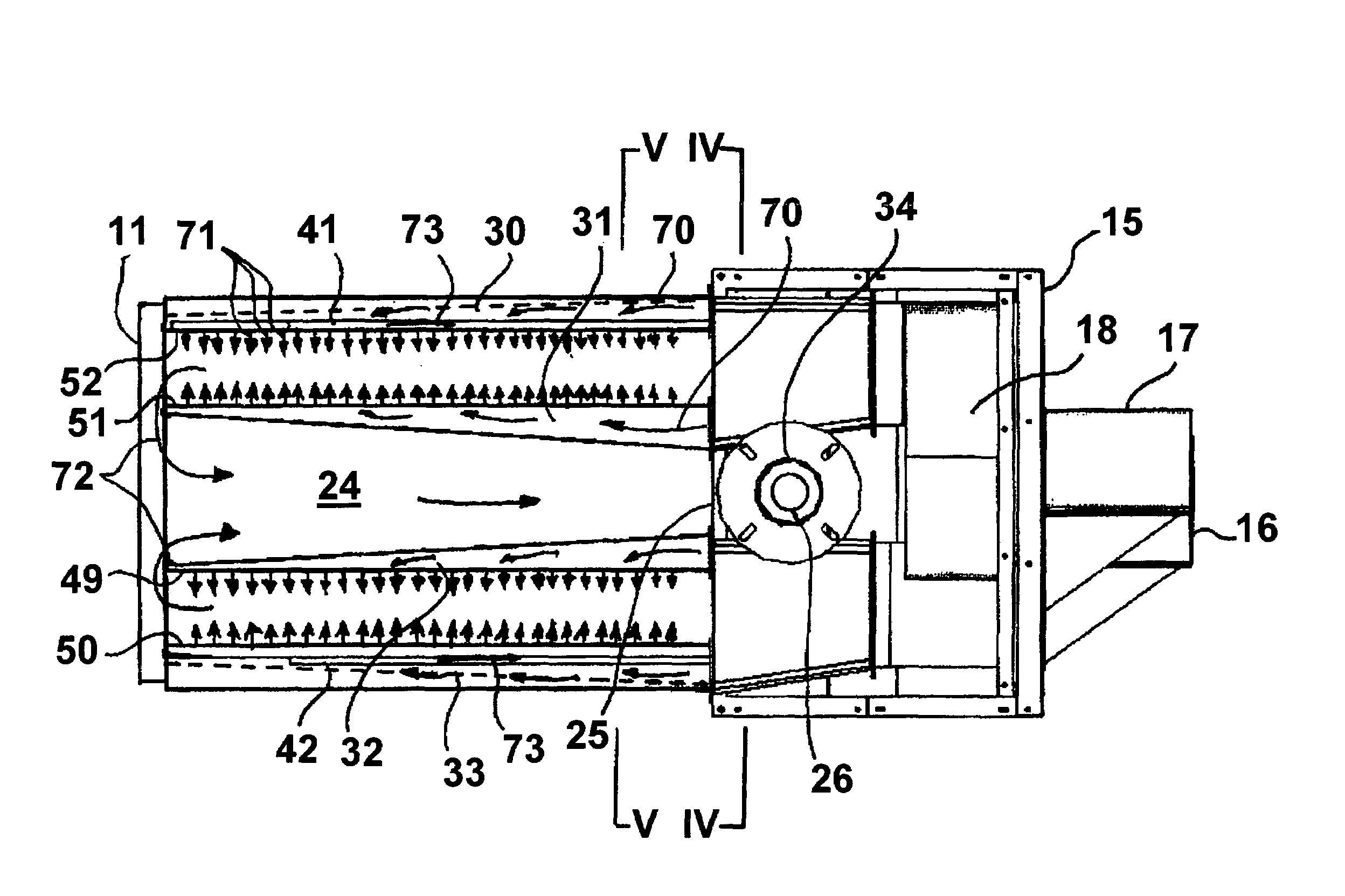
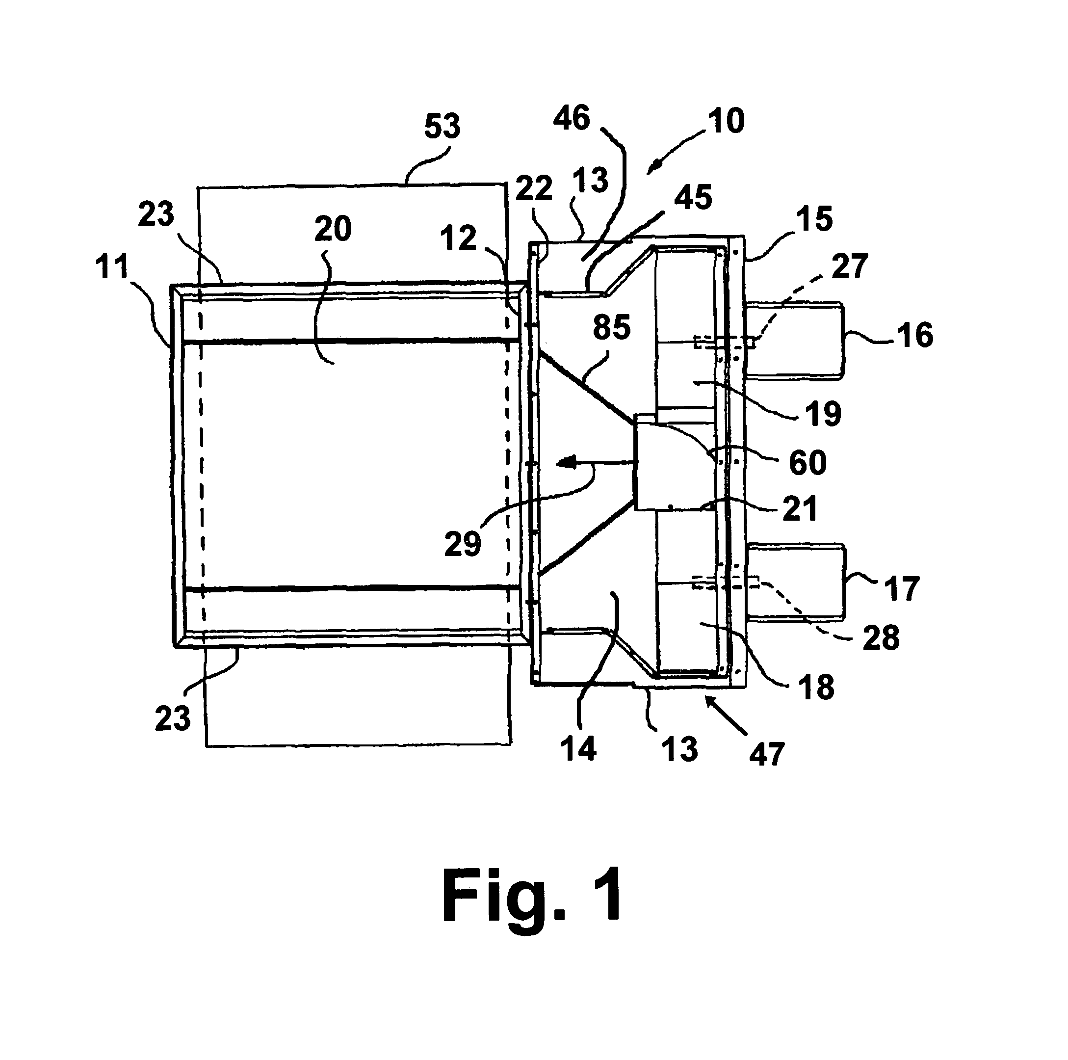
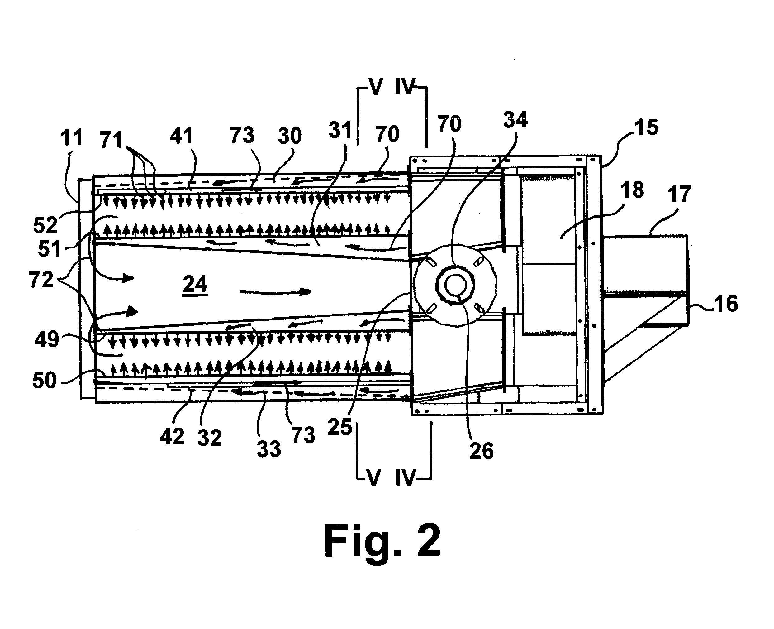
[0020]As shown in FIG. 1, dual conveyor oven 10 comprises a blower box 47 defined by a blower box back wall 15, blower box sidewalls 13 and blower box front wall 22 disposed opposite blower box back wall 15. Disposed within blower box 47 is air plenum 14 having plenum sidewalls 45. Disposed between plenum sidewalls 45 and blower box sidewalls 13 is an insulating material 46. Disposed adjacent to air plenum 14 is a heating space defined by front wall 11, oppositely disposed back wall 12 and side walls 23. Although shown as separate walls, back wall 12 of the heating space and blower box front wall 22 may be formed as a single wall, common to both the heating space and blower box 47. Disposed within air plenum 14 are two blowers 18 and 19, each of which comprises a motor, 17 and 16, respectively, external to air plenum 14. Each motor 16, 17 comprises a drive shaft 27, 28 which is oriented parallel to the direction of air flow from air plenum 14 into the heating space as indicated by a...


PUM


Abstract

A dual conveyor jet impingement oven having a blower box with at least one air inlet opening and at least two air outlet openings and a heating space adjacent to and in fluid communication with the blower box. Disposed within the heating space are two spaced apart pairs of spaced apart heated air distribution plenums, which form a central return air conduit therebetween. The central return air conduit has a return air outlet end in fluid communication with the blower box and the spaced apart heated air distribution plenums have a heated air inlet opening in fluid communication with the at least two air outlet openings. A horizontal heating surface is disposed between each pair of spaced apart heated air distribution plenums, each of which has a perforated heated air distribution plate facing the horizontal heating surface.

Description

BACKGROUND OF THE INVENTION[0001]1. Field of the Invention[0002]This invention relates to ovens for cooking foods, in particular commercial conveyor ovens typically employed in baking foods, such as pizzas and the like. It will, however, be apparent to those skilled in the art that such conveyor ovens are suitable for use in a variety of non-food related applications, and commercial conveyor ovens for non-food related applications are deemed to be within the scope of this invention.[0003]2. Description of Related Art[0004]Impingement ovens are primarily employed in fast food restaurants for rapid cooking of foods such as pizzas, pre-cooked meals, cookies and the like. Such ovens employ heated air streams which impinge directly upon the surface of the food being cooked. Such ovens typically employ an air handling system, which is responsible for the supply and distribution of heated air to the food and a heating chamber or space in which the food is actually cooked. The food is typic...

Claims


Application Information

Patent Timeline
Patent Type & Authority Patents(United States)
IPC IPC(8): F24C15/32A21B1/24
CPCA21B1/245
Inventor HEBER, ALBERT J.VASAN, LAXMINARASIMHANCOLE, JAMES T.
Owner GAS TECH INST
Why Eureka
Try Eureka