Ion source assembly for ion implantation apparatus and a method of generating ions therein

a technology of ion source assembly and ion implantation apparatus, which is applied in the direction of mass spectrometers, nuclear engineering, stability-of-path spectrometers, etc., can solve the problems of wasting a substantial amount of silicon, unable to optimize the way of forming crystalline silicon bodies for photovoltaic cells, and unable to meet the requirements of photovoltaic cells

Inactive Publication Date: 2011-05-10
NEUTRON THERAPEUTICS LLC
View PDF15 Cites 19 Cited by
  • Summary
  • Abstract
  • Description
  • Claims
  • Application Information

AI Technical Summary

Problems solved by technology

Nevertheless, a way of forming crystalline silicon bodies optimized for photovoltaic cells has remained elusive.
This process, which typically yields a silicon wafer thicker than 150 μm, wastes a substantial amount of silicon by consuming up to 50% of the silicon body in kerf loss and delivering a much greater thickness than is needed for useful photovoltaic devices.
The films produced this way have found application in forming silicon-on-insulator structures but have been cost-prohibitive for solar cells.
Also at thickness well under 1 μm, the films may be so thin as to make efficient light-capturing difficult.
Boosting the energy of ion implant could increase the film thickness, but this adaptation would make the films even more expensive and less economical for photovoltaic cells.

Method used


Image

  • Ion source assembly for ion implantation apparatus and a method of generating ions therein
  • Ion source assembly for ion implantation apparatus and a method of generating ions therein
  • Ion source assembly for ion implantation apparatus and a method of generating ions therein

Examples


Embodiment Construction

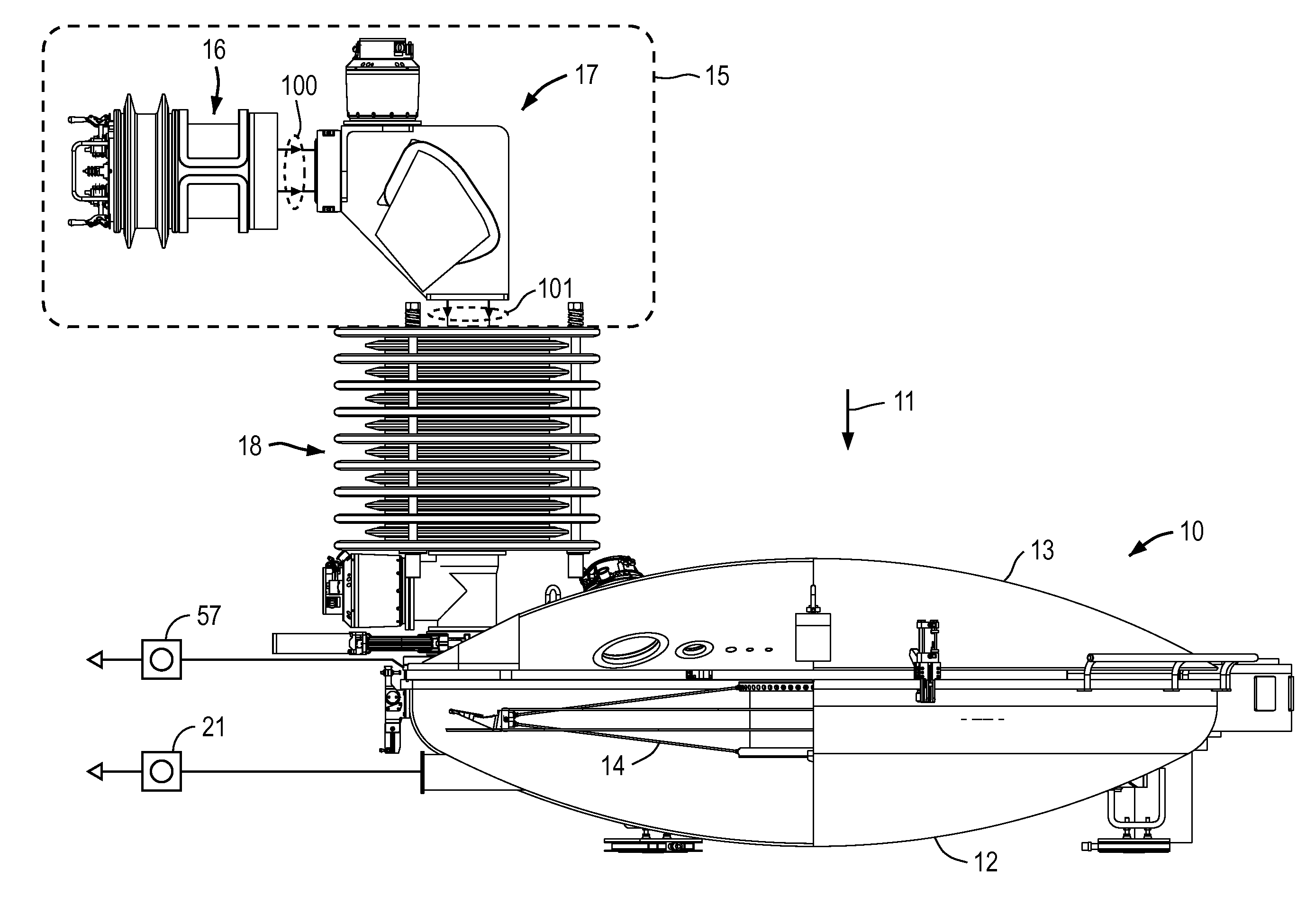
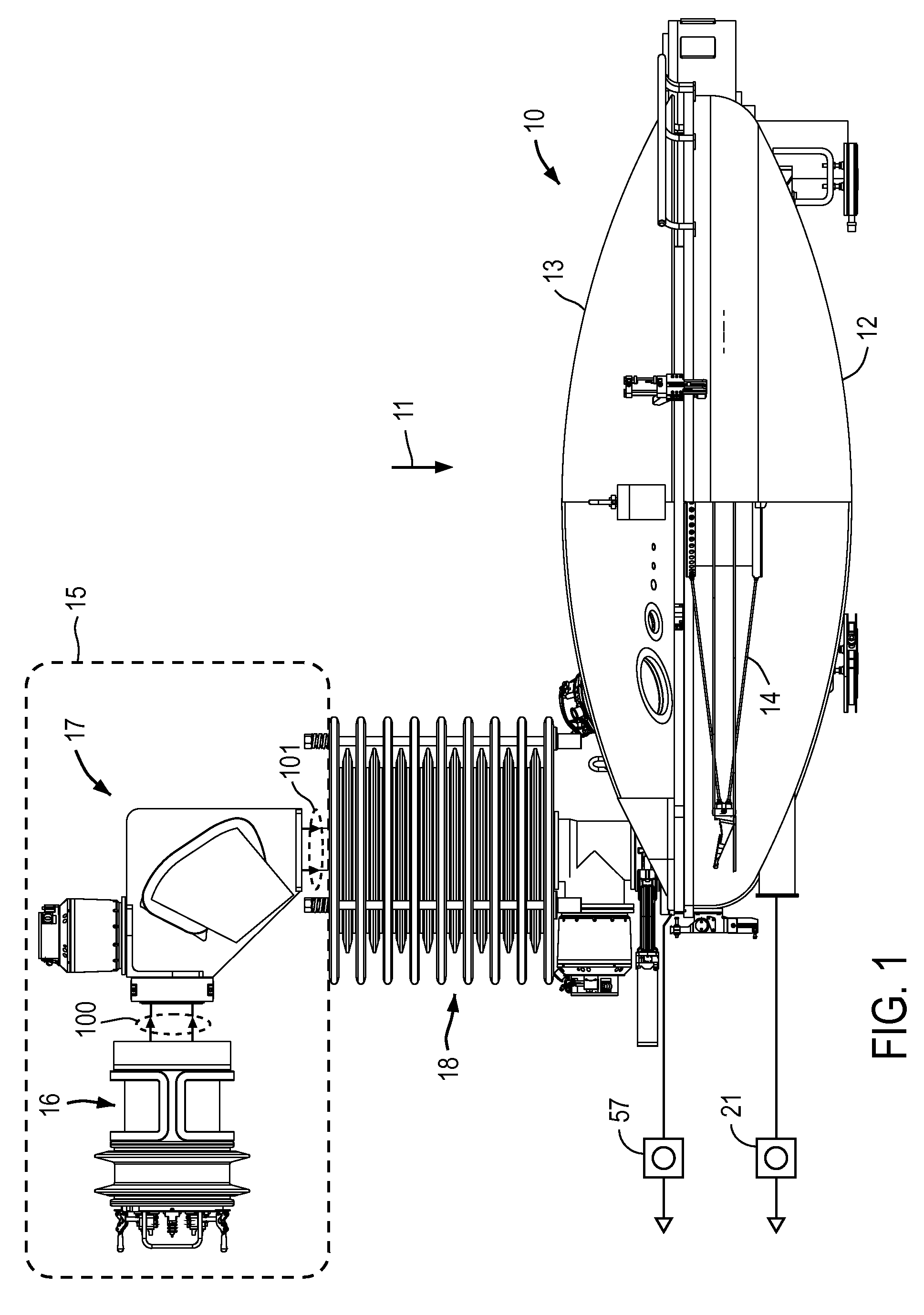
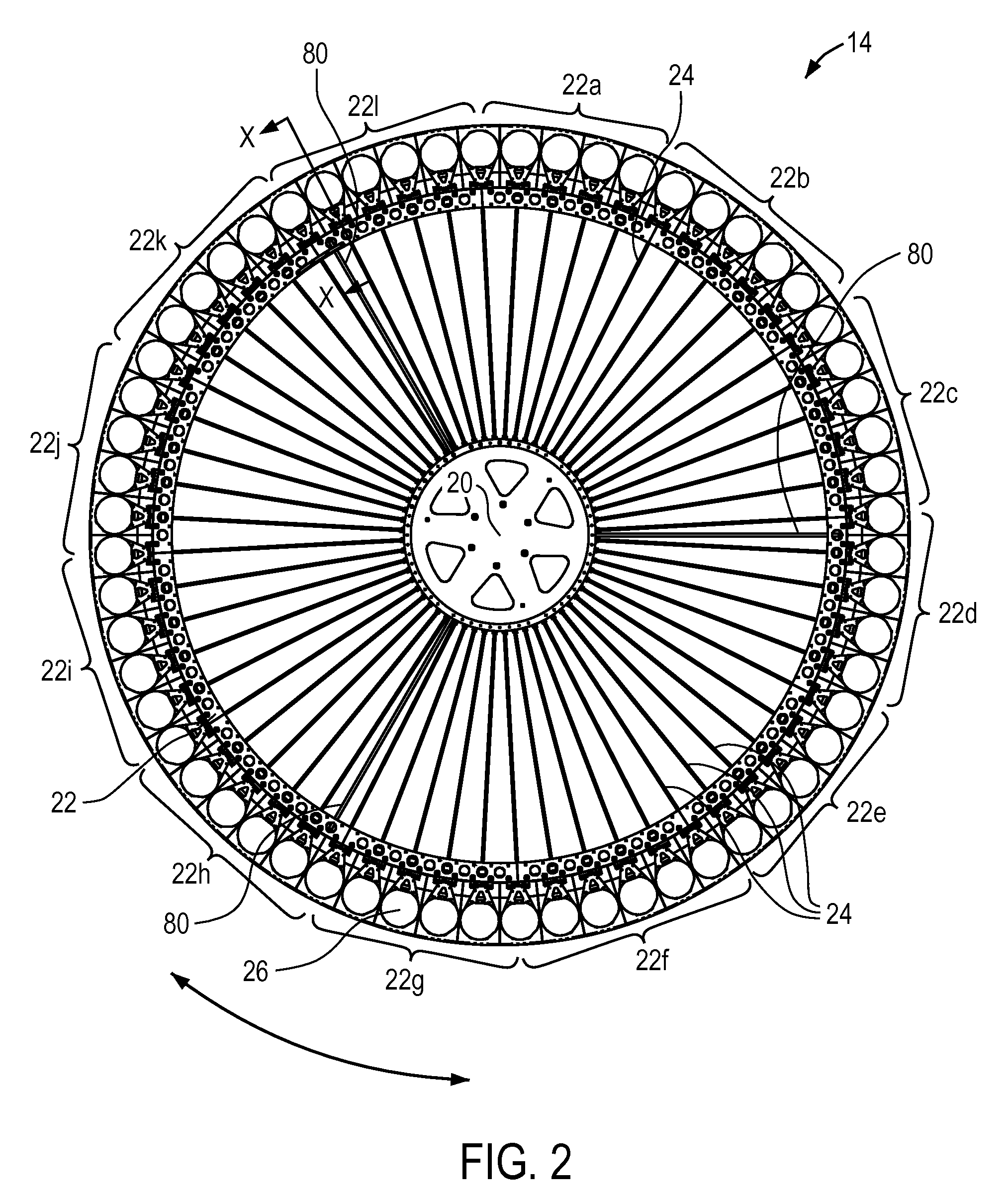
[0036]FIG. 1 is a schematic illustration of ion implantation apparatus which is an embodiment of the present invention. Ion implantation is conducted in a vacuum environment and the main operative features of the embodiment are contained within a vacuum chamber. In the illustrated embodiment in FIG. 1, the vacuum chamber is shown in three interconnected parts. The first part is a process chamber 10 which has a circular profile when viewed from above in FIG. 1 along the direction of arrow 11. The process chamber 10 comprising a part spherical lower wall section 12 and an opposed part spherical upper wall section 13, forming a disc shaped vacuum enclosure which is thickened at the center of the disc. This process chamber 10 contains a process wheel 14 extending in the plane of the disc chamber 10 for rotation about a vertical axis aligned substantially with the center of the disc. Substrates for processing are carried in the process chamber 10 about the periphery of the wheel 14, as w...


PUM


Abstract

A hydrogen ion implanter for the exfoliation of silicon from silicon wafers uses a large scan wheel carrying 50+ wafers around its periphery and rotating about an axis. In one embodiment, the axis of rotation of the wheel is fixed and a ribbon beam of hydrogen ions is directed down on a peripheral edge of the wheel. The ribbon beam extends over the full radial width of wafers on the wheel. The beam is generated by an ion source providing an extracted ribbon beam having at least 100 mm major cross-sectional diameter. The ion source may use core-less saddle type coils to provide a uniform field confining the plasma in the ion source. The ribbon beam may be passed through a 90° bending magnet which bends the beam in the plane of the ribbon.

Description

RELATED APPLICATIONS[0001]This application is related to Ryding et al., U.S. patent application Ser. No. 12 / 494268, “Ion Implantation Apparatus and Method for Fluid Cooling,” Glavish et al., U.S. patent application Ser. No. 12 / 494270, “Ion Implantation Apparatus and Method,” Ryding et al., U.S. patent application Ser. No. 12 / 494269, “Ion Implantation Apparatus,” each filed on even date herewith, owned by the assignee of the present application, and hereby incorporated by reference.BACKGROUND[0002]1. Field of the Invention[0003]This invention relates to ion implantation apparatus to implant ions into planar workpieces. Specific applications of the ion implantation apparatus include the production of lamina of crystalline semiconductor material, such as silicon. Such silicon laminae may be used for the production of photovoltaic cells.[0004]2. Background Information[0005]As the demand for renewable energy based on renewable sources increases, the implementation of photovoltaic technol...

Claims


Application Information

Patent Timeline
Patent Type & Authority Patents(United States)
IPC IPC(8): H01J37/317H01J1/50H01J27/02H01J37/08
CPCH01J37/08H01J37/3171H01J2237/083
Inventor GLAVISH, HILTONRYDING, GEOFFREYSMICK, THEODORE H.
Owner NEUTRON THERAPEUTICS LLC
Why Eureka
Try Eureka