High field NMR permanent magnetic structure

Inactive Publication Date: 2007-04-03
BRK WIRELESS COMPANY INC AN ILLINOIS
View PDF14 Cites 21 Cited by
  • Summary
  • Abstract
  • Description
  • Claims
  • Application Information

AI Technical Summary

Benefits of technology

[0005]An object of the present invention is an improved NMR system that provi

Problems solved by technology

The design of permanent magnetic structures especially for field levels above 1 Tesla (T) faces the problems of

Method used


Image

  • High field NMR permanent magnetic structure
  • High field NMR permanent magnetic structure
  • High field NMR permanent magnetic structure

Examples


Embodiment Construction

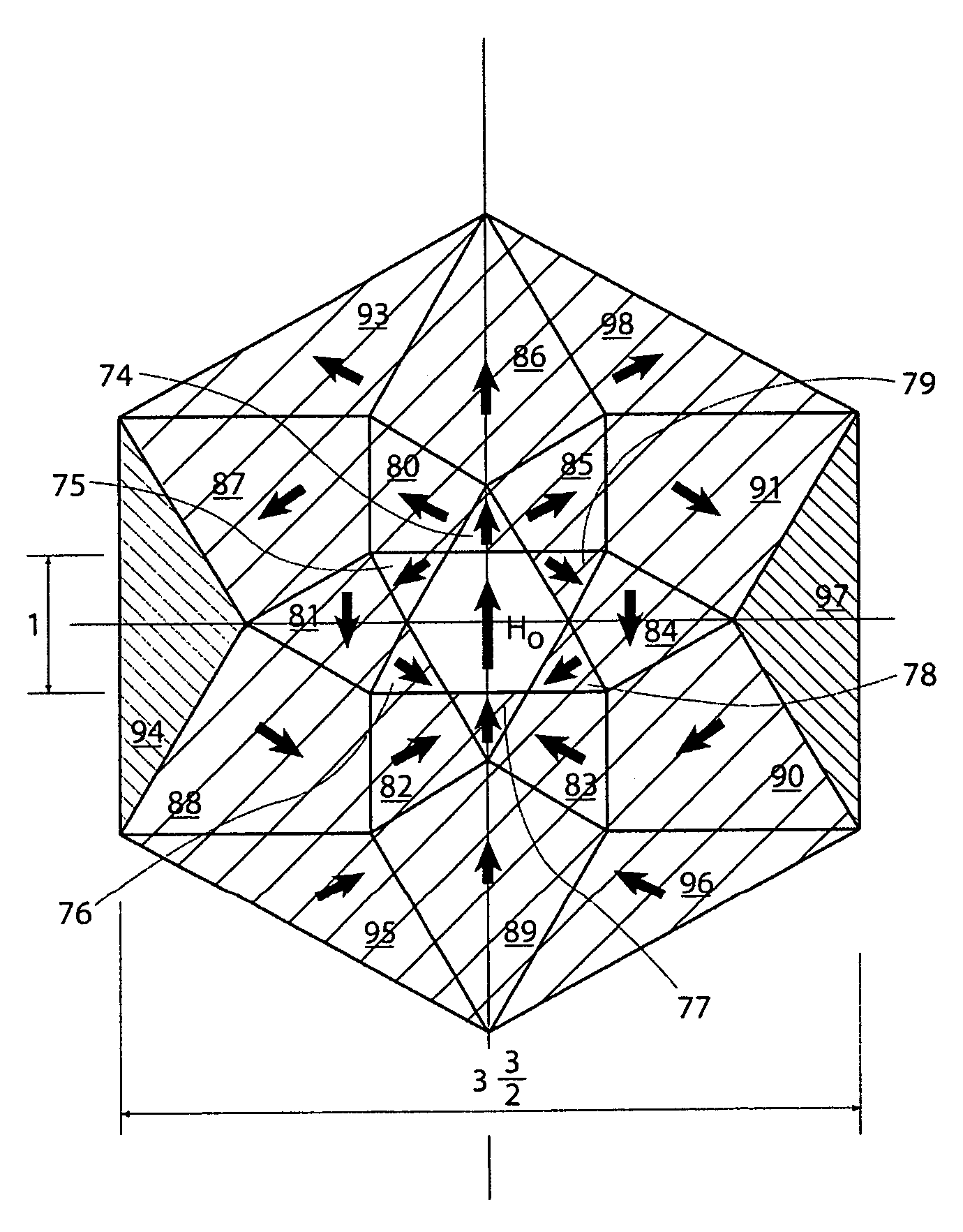
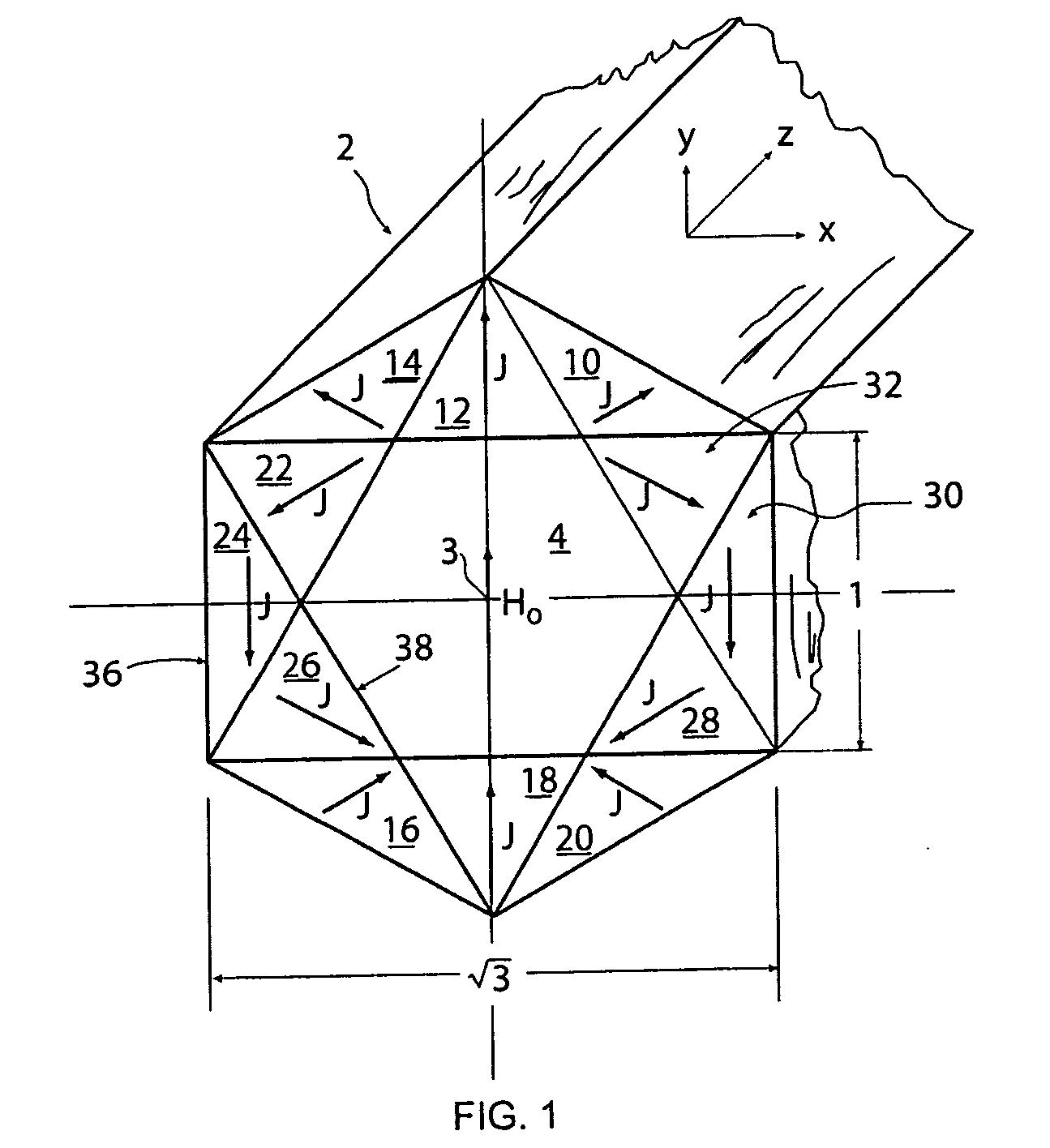
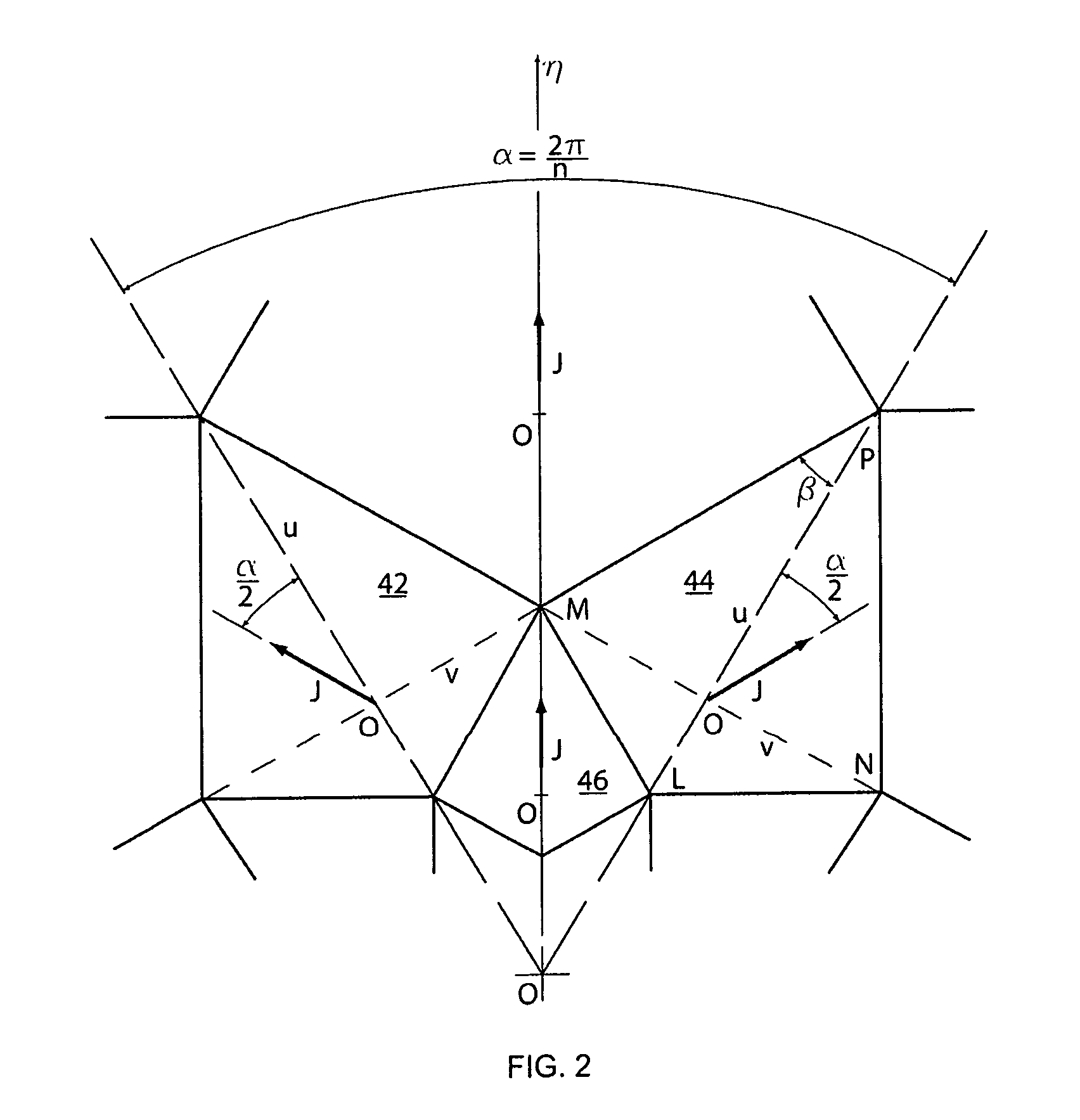
[0019]For a better understanding of the present invention, the reader is urged to read the many technical papers which I alone or with others published and which describe various configurations of NMR imaging systems as well as various schemes for compensating for magnetic field disturbances in composite structures that have been characterized as yoked, yokeless, or hybrid magnets. Also reference is made to the referenced Abele book and Holback paper and also my papers entitled “Field Computation In Permanent Magnets”, IEEE Transactions of Magnetics, 28, No. 1, Jan. 1992, Pgs. 931–934; and “Generation of Highly Uniform Field With Permanent Magnets”, J. Appl. Phys., 76(10), 15 Nov. 1994, Pgs. 6247–6252. Particular attention is also directed to issued U.S. Pat. Nos. 5,494,222; 5,790,006, and 6,265,959 which describe some of the problems of fabricating magnetic structures with NMR imaging uniform fields and some solutions to those problems, the contents all of which patents and publica...


PUM


Abstract

A magnetic structure enclosing a prismatic cavity of regular polygonal cross-section is presented. The structure contains the field within the volume of the magnet without the need of an external ferromagnetic yoke, which makes it suitable for generating fields of several Tesla. The structures presented are designed to generate uniform fields for NMR studies, especially high intensity fields.

Description

BACKGROUND OF INVENTION[0001]The invention is directed to a permanent magnetic structure used to establish a uniform examination field in a nuclear magnetic resonance (NMR) system.[0002]Such systems are well known as magnetic resonance imaging (MRI) instruments for medical imaging of live patients. Actually, such instruments were first developed on a small scale for laboratory use for the examination of inanimate and small animate objects and subsequently on a larger scale for application to human objects. In both applications, usually the higher the intensity of the uniform field in the region of interest, the better the resolution or other output data received from the instrument.[0003]The design of permanent magnetic structures especially for field levels above 1 Tesla (T) faces the problems of saturation of ferromagnetic material as well as the limitations of the remanence of available magnetic alloys.[0004]One category of permanent magnets that is not affected by these limitati...

Claims


Application Information

Patent Timeline
IPC IPC(8): H01F1/00H01F3/00H01F7/00
CPCG01R33/383H01F7/0278
Inventor ABELE, MANLIO
Owner BRK WIRELESS COMPANY INC AN ILLINOIS
Why Eureka
Try Eureka