Electronic device electromagnetic environmental effect test system and test method under electromagnetic pulse compound field environment

A technology of electronic equipment and electromagnetic pulse, which is applied in the direction of measuring electricity, measuring electrical variables, measuring devices, etc., can solve the problems such as the standardization and rationality of the electromagnetic environment effect test of electronic equipment without test methods, so as to ensure the standardization and rationality , the effect of improving accuracy

Active Publication Date: 2019-02-19
INST OF DEFENSE ENG ACADEMY OF MILITARY SCI PLA CHINA
View PDF14 Cites 19 Cited by
  • Summary
  • Abstract
  • Description
  • Claims
  • Application Information

AI Technical Summary

Problems solved by technology

In domestic research, there are neither test requirements nor suitable test methods for the effect test of electronic equipment in the low-frequency, low-impedance electromagnetic pulse c

Method used


Image

  • Electronic device electromagnetic environmental effect test system and test method under electromagnetic pulse compound field environment
  • Electronic device electromagnetic environmental effect test system and test method under electromagnetic pulse compound field environment
  • Electronic device electromagnetic environmental effect test system and test method under electromagnetic pulse compound field environment

Examples


Embodiment Construction

[0032] The present invention will be further described in detail below in conjunction with the accompanying drawings and specific embodiments.

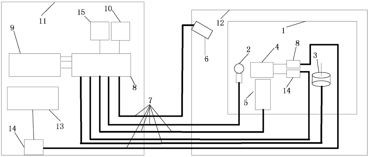
[0033] The invention discloses a test system and test method for the electromagnetic environment effect of electronic equipment in the electromagnetic pulse compound field environment, and the attached figure 1It is a schematic diagram of the layout of the test system, including test equipment and test equipment, wherein the test equipment is located in the test test area 12, and the uniform field test area 1 and the camera 6 for monitoring the uniform field test area 1 are set in the test test area 12. Place the electronic equipment under test 4, the attitude console 5 under test, the magnetic field sensor 2 and the electric field sensor 3 in the area 1, and the test equipment includes an oscilloscope 9, a video monitor 10, an electronic equipment working state controller 13 and an attitude adjustment controller 15,

[0034] The elec...


PUM

PropertyMeasurementUnit
Lengthaaaaaaaaaa

Abstract

The invention discloses an electronic device electromagnetic environmental effect test system and test method under an electromagnetic pulse compound field environment. A tested electronic device is fixed to a tested posture control table and placed in a uniform field test area, the tested electronic device is set to a certain working state by using an electronic device working state controller, and the tested posture control table is adjusted, a magnetic field control circuit and an electronic field control circuit are controlled to set a magnetic field amplitude value and an electronic fieldamplitude value, a magnetic field generator and an electronic field generator are subjected to linkage and trigger, and a compound field is formed to perform an irradiation effect test. The magneticfield amplitude value, the electronic field amplitude value and delaying time are continuously changed from low to high, responding phenomenon and responding signals of the tested electronic device under different interference source parameters are recorded, and effect laws are analyzed. The electronic device electromagnetic environmental effect test system and test method under the electromagnetic pulse compound field environment ensure standardization and rationality of the electromagnetic environmental effect test of the electronic device, improve accuracy of the electromagnetic environmental effect test of the electronic device, and are suitable for carrying out relative research work of an electromagnetic pulse compound field environmental effect test of a ground nuclear explosion source area.

Description

technical field [0001] The invention relates to the technical field of electromagnetic interference testing methods, in particular to a method for testing electromagnetic environment effects of electronic equipment in a low-frequency, low-impedance electromagnetic pulse composite field environment. Background technique [0002] Due to the extreme asymmetry of the explosive environment, when a nuclear weapon explodes on the ground, its source area can produce a peak magnetic induction intensity of hundreds of gauss, a pulse duration of milliseconds, a main energy spectrum ranging from 10Hz to 100kHz, and a wave impedance less than 377Ω. Low-frequency low-impedance pulse strong magnetic field, the rise time of the electric field generated by it is 10-100ns, the half-wave width is 1ms, and the intensity is as high as 100kV / m. The electromagnetic pulse environment in the ground nuclear explosion source area has the characteristics of high intensity, high energy, low frequency, l...

Claims


Application Information

Patent Timeline
IPC IPC(8): G01R31/00
CPCG01R31/001
Inventor 熊久良闫民华李跃波刘锋杨杰张耀辉潘征何为黄刘宏
Owner INST OF DEFENSE ENG ACADEMY OF MILITARY SCI PLA CHINA
Why Eureka
Try Eureka