
Dual view display system using a transparent display

Active Publication Date: 2012-01-26
APTIV TECH LTD
View PDF6 Cites 90 Cited by
  • Summary
  • Abstract
  • Description
  • Claims
  • Application Information

AI Technical Summary

Problems solved by technology

While such displays may be viewed from either side, the image on one side is typically a mirror or reverse image of the opposite side, and so makes the viewing images such as text or asymmetrical objects difficult for the person seeing the mirrored or reversed image.

Method used


Image

  • Dual view display system using a transparent display
  • Dual view display system using a transparent display
  • Dual view display system using a transparent display

Examples


Embodiment Construction

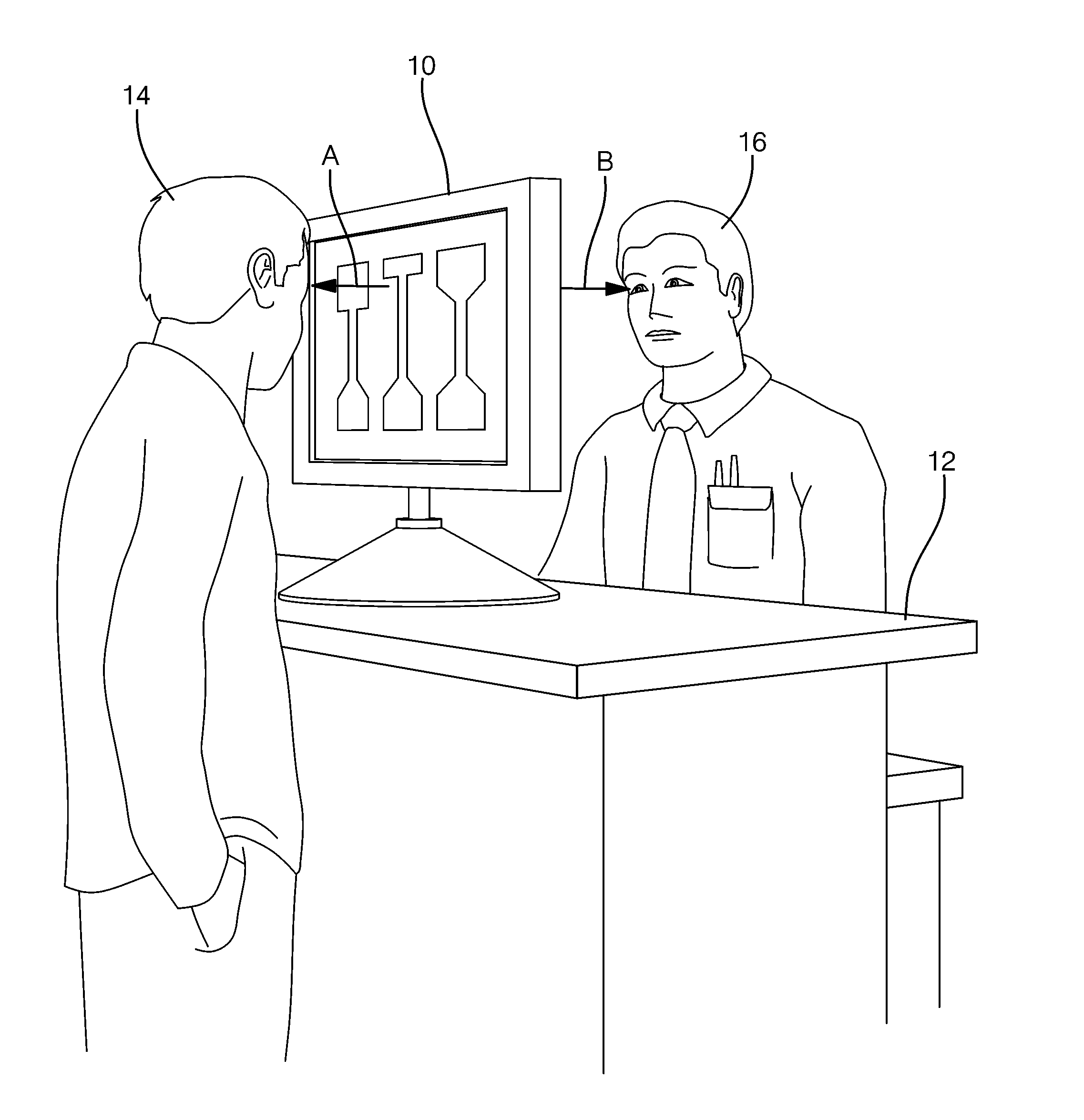
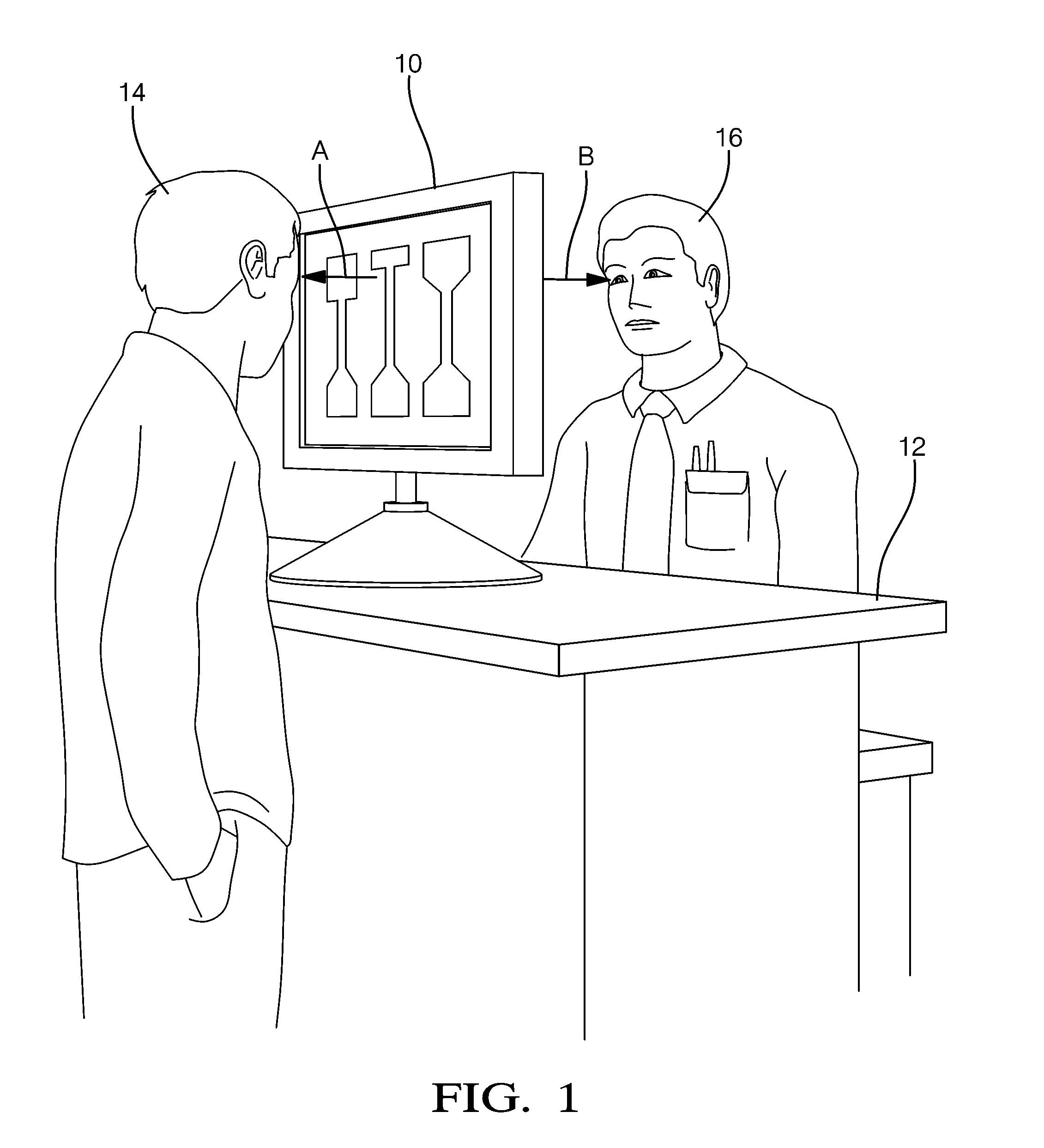
[0011]In accordance with an embodiment of a dual view display system 10 for displaying properly oriented images in substantially opposite directions A and B, FIG. 1 illustrates a non-limiting example of the system 10 positioned on a service counter 12 at a retail store, for example an automotive parts store. As used herein, displaying properly oriented images means that the dual view display system 10 includes features to overcome the problem of the images on the opposite sides of the transparent display being reversed or minor images of each other, as will be described in more detail below. The system 10 is configured so that, as illustrated in this example, a customer 14 and a sales person 16 can view information from opposite direction A and B on opposite sides of the dual view display system 10. In some instances, it may be desirable for the customer 14 to view the same information that is viewed by the sales person 16, for example to identify an automotive part the customer 14 ...


PUM


Abstract

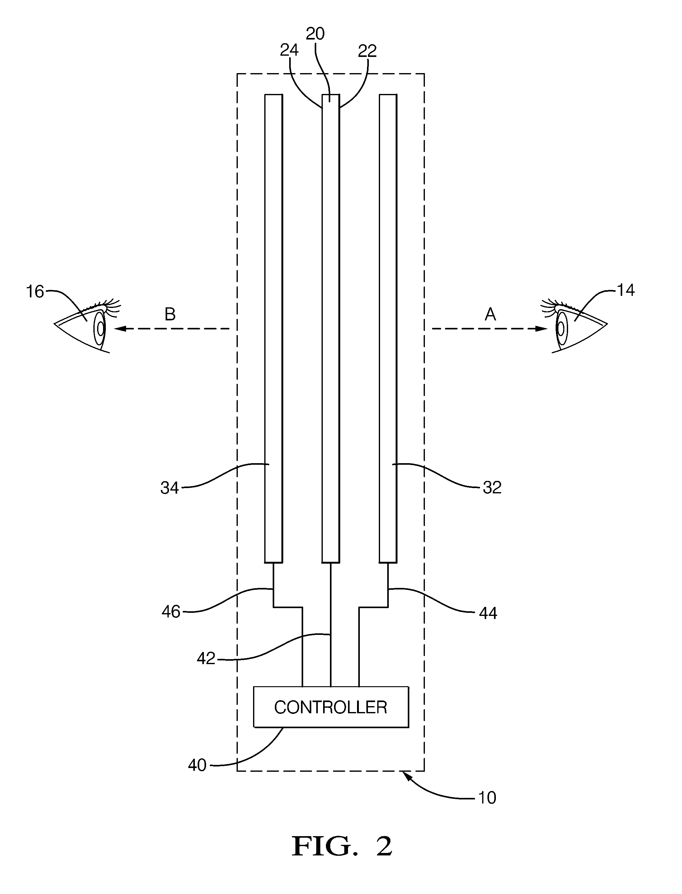
A dual view display system to display two different images in substantially opposite direction using a single transparent display to time-multiplex the images and shutter devices to alternately block each side from being viewed according to the image being displayed.

Description

TECHNICAL FIELD OF INVENTION[0001]The invention generally relates to displays for displaying images or information, and more particularly relates to a system that time-multiplexes a single transparent display with different images, and uses light valves or shutter devices to display different images in substantially opposite directions from opposite sides of the transparent display.BACKGROUND OF INVENTION[0002]Transparent panel type displays capable of being viewed from substantially opposite sides are known. For example, a transparent organic light emitting diode (OLED) type display naturally emits light from both sides of the display. Such displays are available from Samsung, NeoView Kolon, and others. Other examples include transparent electroluminescent (EL) displays and transparent liquid crystal display (LCD). While such displays may be viewed from either side, the image on one side is typically a mirror or reverse image of the opposite side, and so makes the viewing images su...

Claims


Application Information

Patent Timeline
IPC IPC(8): G09G5/00
CPCG02F1/13306G02F1/1347G02F2001/133342G09G3/003G02F1/13338G09G3/36G09G3/38G09G2300/023G09G3/348G02F1/133342
Inventor KUHLMAN, FREDERICK F.HARBACH, ANDREW P.PARKER, RICHARD D.SARMA, DWADASI H.R.
Owner APTIV TECH LTD
Learn More