Vibrating Mirror Element and Optical Scanner

a mirror element and optical scanner technology, applied in the direction of optics, optical elements, instruments, etc., can solve the problems of disadvantageous inclines, disadvantageous inclines of the end, and the disadvantageous inclines of the mirror portion connected to the free end with respect to the fixed end, so as to achieve the effect of suppressing the size increas

Inactive Publication Date: 2012-02-02
FUNAI ELECTRIC CO LTD
View PDF1 Cites 12 Cited by
  • Summary
  • Abstract
  • Description
  • Claims
  • Application Information

AI Technical Summary

Benefits of technology

[0007]The present invention has been proposed in order to solve the aforementioned problems, and an object of the present invention is to provide a vibrating mirror element capable of suppressing size

Problems solved by technology

In the optical reflecting element disclosed in the aforementioned Japanese Patent Laying-Open No. 2009-192967, however, the fixed end of the meandering vibrator is fixed to the outer frame body on the side opposite to the mirror portion in the direction X, and hence the fixed end is so separated from the mirror portion in the direction X (extensional direction of the axis) that the size of the optical reflecting element is disadvantageously easily increased in the direction X (extensional direction of the axis).
If the plurality of pi

Method used


Image

  • Vibrating Mirror Element and Optical Scanner
  • Vibrating Mirror Element and Optical Scanner
  • Vibrating Mirror Element and Optical Scanner

Examples


Embodiment Construction

[0045]An embodiment of the present invention is now described with reference to the accompanying drawings.

[0046]First, the structure of a vibrating mirror element 100 according to the embodiment of the present invention

[0047]described with reference to FIGS. 1 to 8.

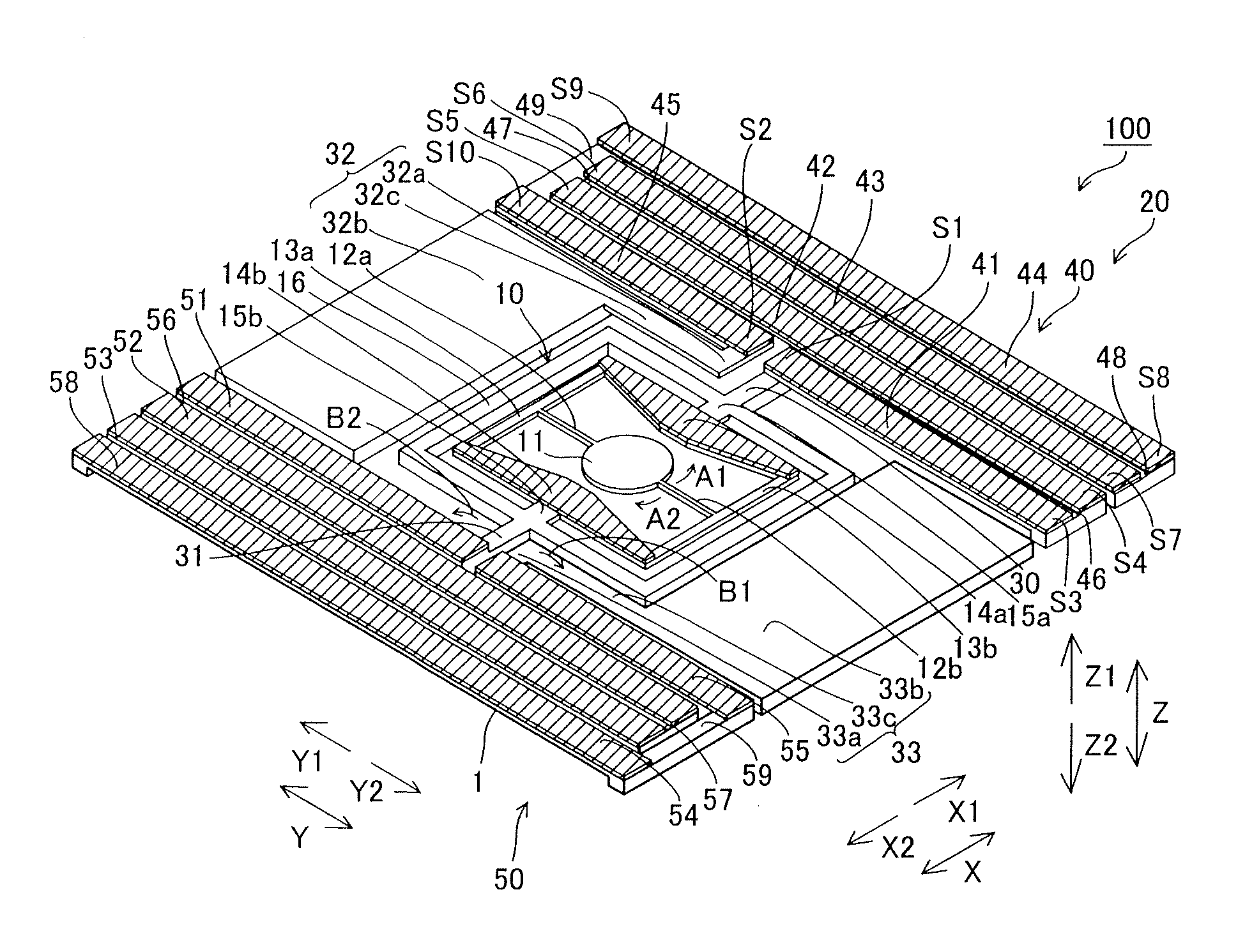
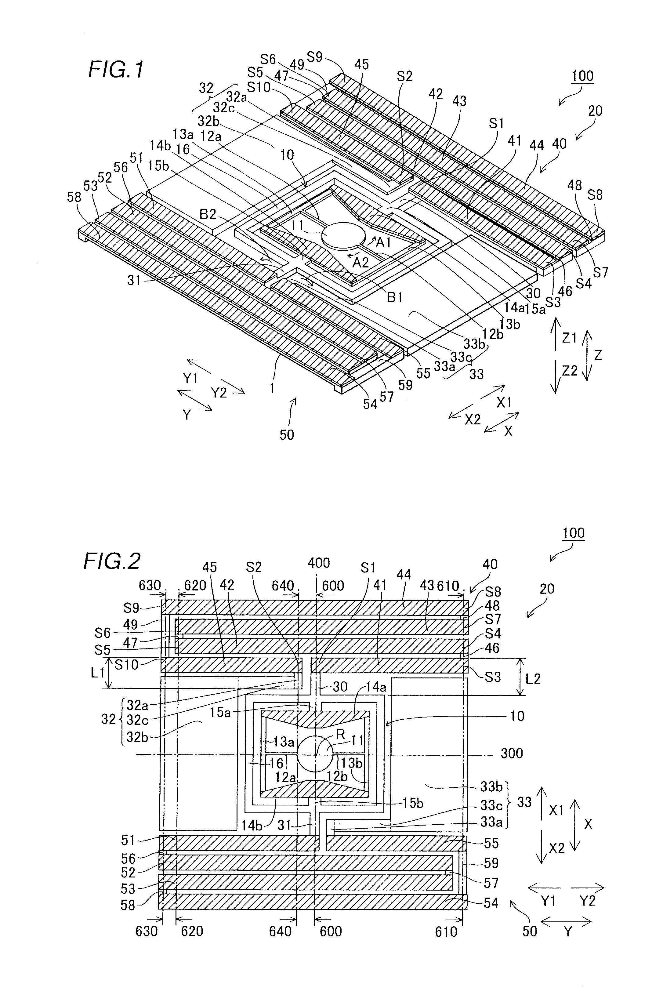
[0048]The vibrating mirror element 100 according to the embodiment of the present invention includes an A-directional optical scanning portion 10 for optically scanning an object in a direction (along arrows A1 and A2) in a prescribed plane with a mirror 11 described later, a B-directional optical scanning portion 20 for optically scanning the object in a direction along arrows B1 and B2 orthogonal to the direction along arrows A1 and A2 with the mirror 11, rotating shafts 30 and 31 connecting the A-directional optical scanning portion 10 and the B-directional optical scanning portion 20 with each other and fixing portions 32 and 33 for fixing the B-directional optical scanning portion 20, as shown in FIGS. 1 and 2.

[0049]...


PUM


Abstract

This vibrating mirror element includes a mirror portion swingable on a first axis, a driving portion, including a free end and a fixed end, for swinging the mirror portion by deformation and a shaft portion provided between the mirror portion and the driving portion to extend along the first axis. The free end of the driving portion is connected to the shaft portion, while the fixed end of the driving portion is fixed on a side of the driving portion closer to the mirror portion and in the vicinity of the shaft portion.

Description

BACKGROUND OF THE INVENTION[0001]1. Field of the Invention[0002]The present invention relates to a vibrating mirror element and an optical scanner, and more particularly, it relates to a vibrating mirror element including a driving portion having a free end connected to a shaft portion and an optical scanner including the vibrating mirror element.[0003]2. Description of the Background Art[0004]A vibrating mirror element including a driving portion having a free end connected to a shaft portion is known in general, as disclosed in Japanese Patent Laying-Open No. 2009-192967, for example.[0005]The aforementioned Japanese Patent Laying-Open No. 2009-192967 discloses an optical reflecting element (vibrating mirror element) including a mirror portion swingable on an axis extending in a first direction (direction X), an inner frame body connected to the mirror portion and swingable on the axis along with the mirror portion, a shaft portion connected to the inner frame body, a meandering v...

Claims


Application Information

Patent Timeline
IPC IPC(8): G02B26/10
CPCG02B26/0858
Inventor MURAYAMA, MANABUINOUE, NAOKI
Owner FUNAI ELECTRIC CO LTD
Why Eureka
Try Eureka