Air blower

a blower and air technology, applied in the direction of positive displacement liquid engines, liquid fuel engines, piston pumps, etc., can solve the problems of noise, reduced air flow of electric fans, safety problems, etc., and achieve the effect of suppressing the size increase of air blowers

Inactive Publication Date: 2012-03-22
SHARP KK
View PDF4 Cites 3 Cited by
  • Summary
  • Abstract
  • Description
  • Claims
  • Application Information

AI Technical Summary

Benefits of technology

[0025]According to this invention, since the ion generating unit also works as the fixing ring for fixing the fan guard onto the motor, the aforementioned effects may be attained while suppressing the size increase of the air blower.

Problems solved by technology

The vaporizable substance diffusing apparatus for a fan according to Japanese Patent Application Laid-Open No. 2007-32351 is, however, attached to the outside of the fan guard of the electric fan, and hence, it is apprehended that an infant or the like may touch the pest control agent, that is, a hazardous substance, and thus, there is a problem in the safety.
Furthermore, when the diffusion vessel is disposed in an air flow path in front of the electric fan, there arises a problem, for example, that the air flow of the electric fan is reduced as well as noise is caused.
Furthermore, since the negative ion generating unit generates negative ions through discharge caused by applying a high voltage to negative and positive electrodes, when the unit is attached to the outside of an electric fan, it is apprehended that an infant or the like may touch the unit, and thus, there is a problem in the safety.

Method used


Image

  • Air blower
  • Air blower
  • Air blower

Examples


embodiment 1

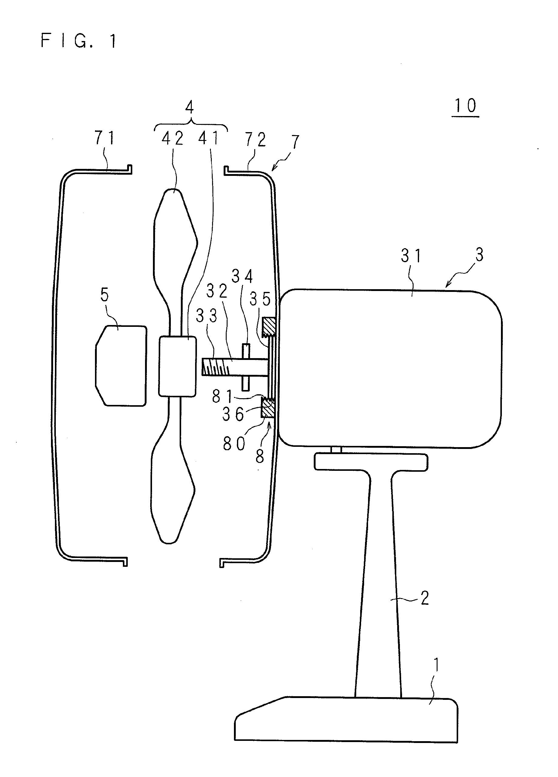
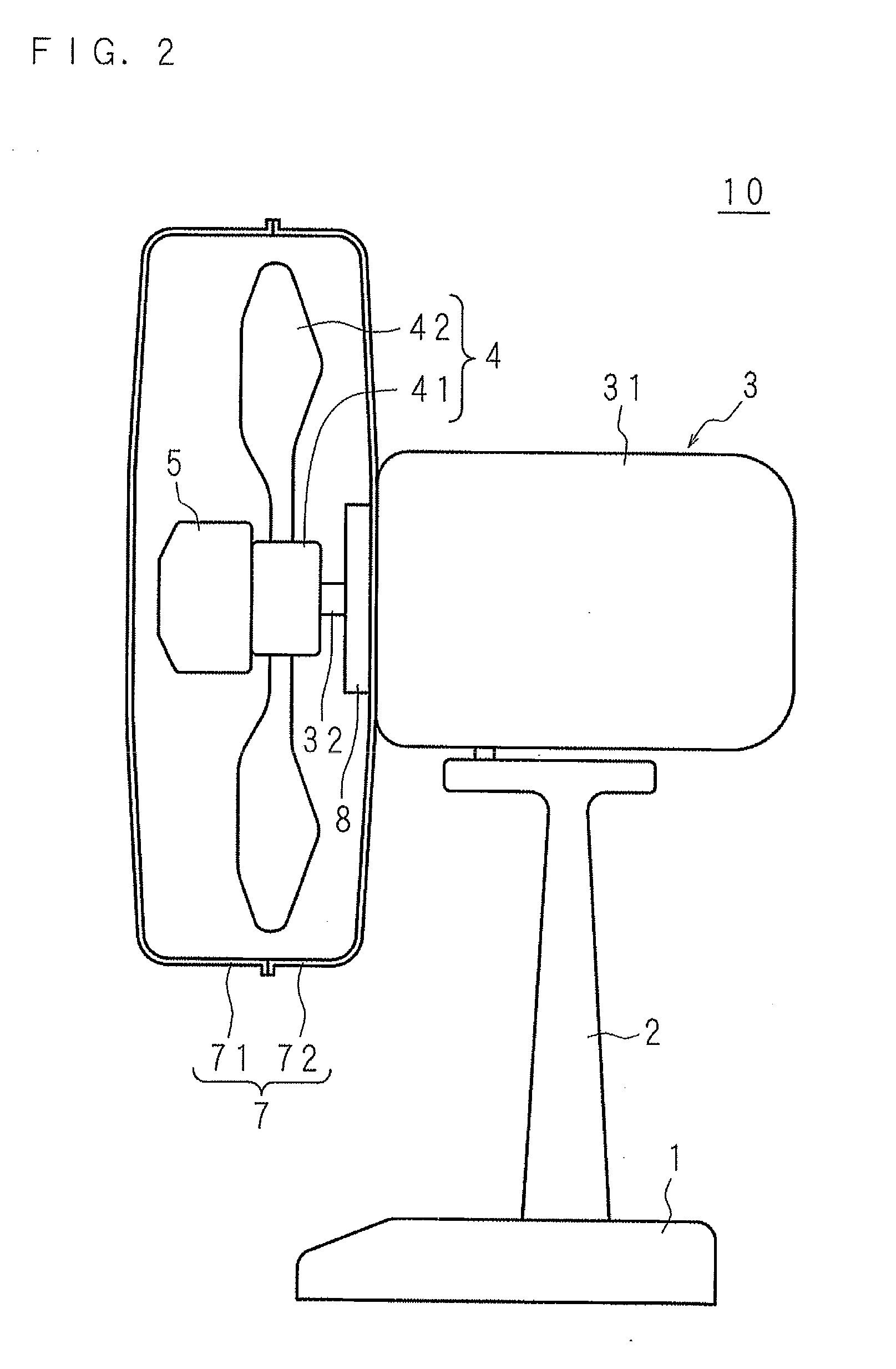
[0047]FIG. 1 is a schematic partially exploded view of an electric fan 10 according to Embodiment 1. FIG. 2 is a schematic outline view of the electric fan 10 of this embodiment.

[0048]In these drawings, a reference numeral 1 denotes a base, which is placed on a floor or the like and is provided with an operation panel (not shown) on its top face. A column 2 stands on the base 1. A motor 3 is provided on the upper end of the column 2. The motor 3 includes a motor body 31 in a substantially circular cylindrical shape and an output shaft 32 projecting from one side of the motor body 31. An external thread part 33 is provided on the tip of the output shaft 32. Furthermore, a fan boss check pin 34 is inserted into the output shaft 32 at right angles against the shaft length direction in a position appropriately away from the tip of the output shaft 32. Moreover, an engaging cylinder 35 is provided on a side of the motor body 31 closer to the output shaft 32 so as to be concentric with th...

embodiment 2

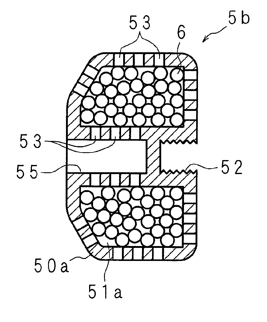
[0066]FIG. 8 is a schematic outline view of an electric fan 20 according to Embodiment 2. The electric fan 20 of Embodiment 2 is different from the electric fan 10 of Embodiment 1 in the shape of the fan nut alone. FIG. 9 is a schematic cross-sectional view of a fan nut 5a.

[0067]The fan nut 5a also works as a hollow vessel for keeping a diffusive substance 6 therein, and includes a storage space 51 for storing the diffusive substance 6 inside a housing 50 in a closed-end cylindrical shape. On one side in the shaft length direction of the fan nut 5a, a recess concentric with the housing 50 and depressed toward the inside of the storage space 51 is formed, and an internal thread part 52a corresponding to an engaging part is formed on the inner circumferential wall of the recess. A contact projection 54 in a circular cylindrical shape having the same inner diameter as the recess is formed to stand concentrically with the recess on one side in the shaft length direction of the fan nut ...


PUM


Abstract

An air blower includes a motor; a fan connected to an output shaft of the motor and rotatively driven by the motor; and a fan nut fixing the fan onto the output shaft of the motor, a diffusive substance is kept in the fan nut provided on the output shaft of the motor, and an ion generating unit is attached to a motor body concentrically with the output shaft. Therefore, the diffusive substance, positive ions and negative ions may be diffused without interrupting blowing and without harmfully affecting the air blowing function. Since the diffusive substance and the ion generating unit are provided inside a fan guard, an infant or the like may be prevented from touching them, and thus, the safety may be secured.

Description

[0001]This application is the National Phase of PCT / JP2010 / 056312 filed on Apr. 7, 2010, which claims priority under 35 U.S.C. §119(a) to Patent Application No. 2009-135304 filed in Japan on Jun. 4, 2009, all of which are hereby expressly incorporated by reference into the present application.BACKGROUND[0002]1. Technical Field[0003]The present invention relates to an air blower capable of diffusing a diffusive substance such as a pest control agent and / or ions.[0004]2. Description of Related Art[0005]Air blowers such as an electric fan having various functions in addition to an air blowing function to send air with a desired flow in a desired direction have been conventionally proposed (see, for example, Japanese Patent Application Laid-Open No. 9-245935 and Japanese Patent Application Laid-Open No. 2007-32351).[0006]An air blower disclosed in Japanese Patent Application Laid-Open No. 9-245935 is additionally provided with a negative ion generating unit for generating negative ions....

Claims


Application Information

Patent Timeline
Patent Type & Authority Applications(United States)
IPC IPC(8): F04B37/00F04B35/01F04B53/00
CPCF04D17/167F04D29/705F04D29/703F04D29/329
Inventor ISHII, HIKOYAMORIMOTO, KATSUSHI
Owner SHARP KK
Why Eureka
Try Eureka