
Photographic Reflector

Active Publication Date: 2012-02-02
LINCO
View PDF5 Cites 10 Cited by
  • Summary
  • Abstract
  • Description
  • Claims
  • Application Information

AI Technical Summary

Benefits of technology

[0006]A primary objective of the present invention is to provide a photographic reflector that can be folded as compactly as desired, easily stored, and convenient in transportation and use.
[0008]With the technical solution provided by the present invention, except for the advantages of quick assembling and convenience in operation, the photographic reflector of the present invention can be folded while not in use, thereby occupying less space and providing convenience in storage and transportation.

Problems solved by technology

Conventional photographic reflectors generally can not be folded as compactly as desired, which occupy a large storage space and are inconvenient in transportation and use.

Method used


Image

  • Photographic Reflector
  • Photographic Reflector
  • Photographic Reflector

Examples


Embodiment Construction

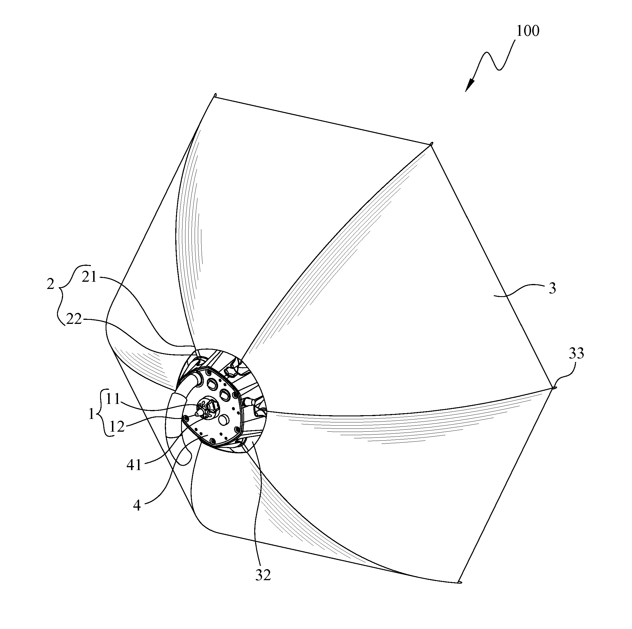
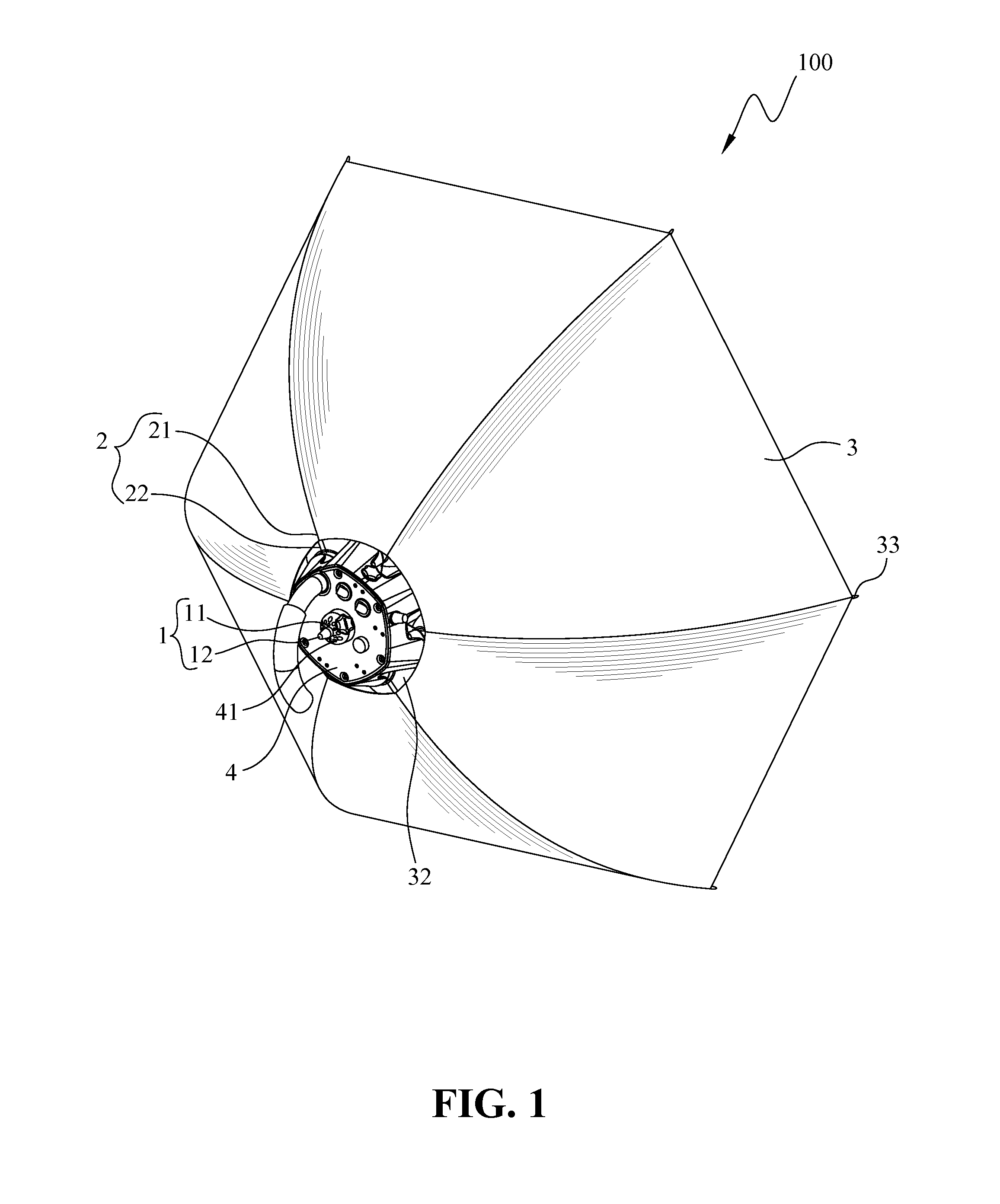
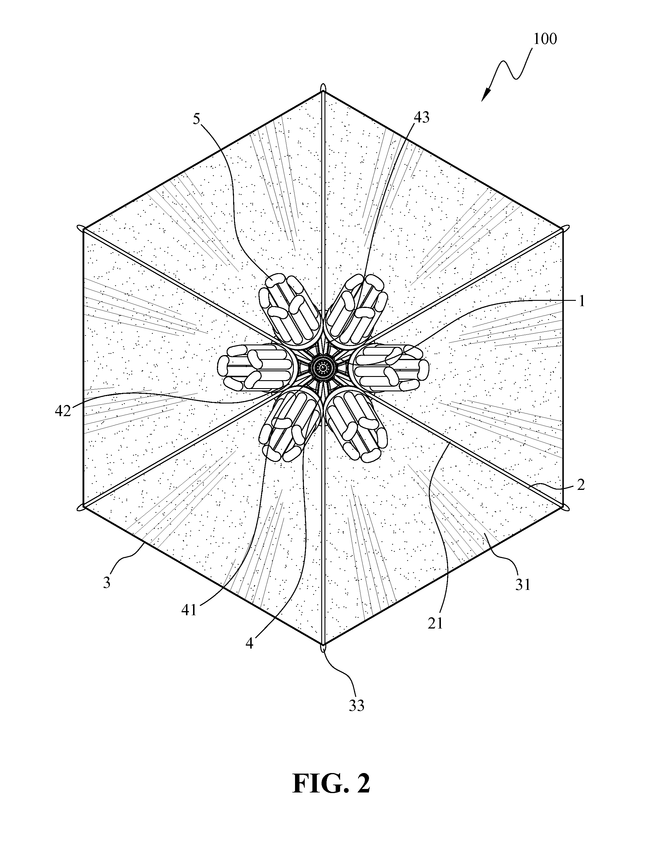
[0015]Please refer to FIG. 1 and FIG. 2. FIG. 1 is a perspective view showing an outside of a photographic reflector according to an embodiment of the present invention, and FIG. 2 is a perspective view showing an inside of the photographic reflector of the present invention. A photographic reflector 100 according to an embodiment of the present invention comprises an engagement unit 1, a support frame 2, a fabric canopy 3, and a lamp holder 4.

[0016]The engagement unit 1 includes an engagement seat 11 and an engagement member 12 moveably mounted in the engagement seat 11. The engagement member 12 is capable of making a relative back-and-forth movement with respect to the engagement seat 11 and being engaged and fastened at a preset location of the engagement seat 11. In this embodiment, the structure of the engagement unit 1 is provided for illustrative purposes only, but not limited thereto. Other structures having the same function can also be adopted for replacements.

[0017]The su...


PUM


Abstract

A photographic reflector includes an engagement unit, a support frame, a fabric canopy, and a lamp holder. The engagement unit includes an engagement seat and an engagement member moveably mounted in the engagement seat. The support frame includes a plurality of ribs and a plurality of stretchers corresponding to each respective rib. One end of each rib is pivotally connected to the engagement seat. One end of each stretcher is pivotally connected to a preset location of the corresponding rib, and the other end of each stretcher is pivotally connected to the engagement member. The fabric canopy is mounted on the ribs of the support frame and has a reflective layer at an inside thereof and a mounting hole defined at a location close to the engagement unit. The lamp holder is mounted in the mounting hole of the fabric canopy. The photographic reflector can be folded as compactly as desired, easily stored, and convenient in transportation and use.

Description

BACKGROUND OF THE INVENTION[0001]1. Field of the Invention[0002]The present invention relates to a lamp reflector, and more particular to a photographic reflector for use in photography.[0003]2. The Prior Arts[0004]In photographing, radio and television, movie making, and live broadcast industries, many photographing, image capturing, and illuminating apparatuses are required. In order to direct light towards a specific direction or area for achieving the required level of illumination, a photographic reflector is often used in photographing. Conventional photographic reflectors generally can not be folded as compactly as desired, which occupy a large storage space and are inconvenient in transportation and use.[0005]Therefore, it is desired to provide an improved photographic reflector.SUMMARY OF THE INVENTION[0006]A primary objective of the present invention is to provide a photographic reflector that can be folded as compactly as desired, easily stored, and convenient in transpor...

Claims


Application Information

Patent Timeline
IPC IPC(8): G03B15/02G03B15/06
CPCG03B15/06
Inventor LIN, CHIEN-TING
Owner LINCO
Learn More