Turbine ring assembly

Active Publication Date: 2012-02-02
GERAKL
View PDF9 Cites 155 Cited by
  • Summary
  • Abstract
  • Description
  • Claims
  • Application Information

AI Technical Summary

Benefits of technology

[0015]According to a feature of the turbine ring assembly, one, or a first one, of the tabs has its end held radially by engaging in a housing of substantially U-shaped section in a one-piece hook-shaped portion of the ring support structure. By way of example, this first tab is the upstream tab. Preferably, the housing of U-shaped section is defined by opposite inner and outer branches, and the inner branch has a length that is shorter than the length of the outer branch.
[0016]According to another feature of the turbine ring assembly, one, or a second one, of the tabs has its end held radially without clearance against an annular surface of the ring support structure by means of a

Problems solved by technology

Thus, such resilient mounting is poorly compatible with the finishing machining that is conventionally performed after initial mounting of the ring sectors in order to confer an almost perfect cylindrical shape to the inside surface of the ring.
In addition, when the tip of a blade on a rotor wheel surr

Method used


Image

  • Turbine ring assembly
  • Turbine ring assembly
  • Turbine ring assembly

Examples


Embodiment Construction

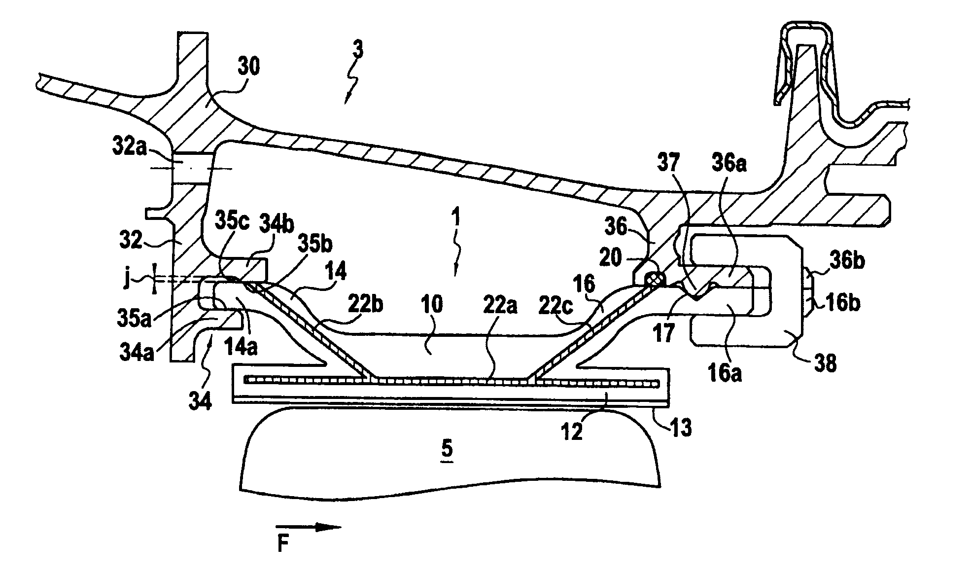
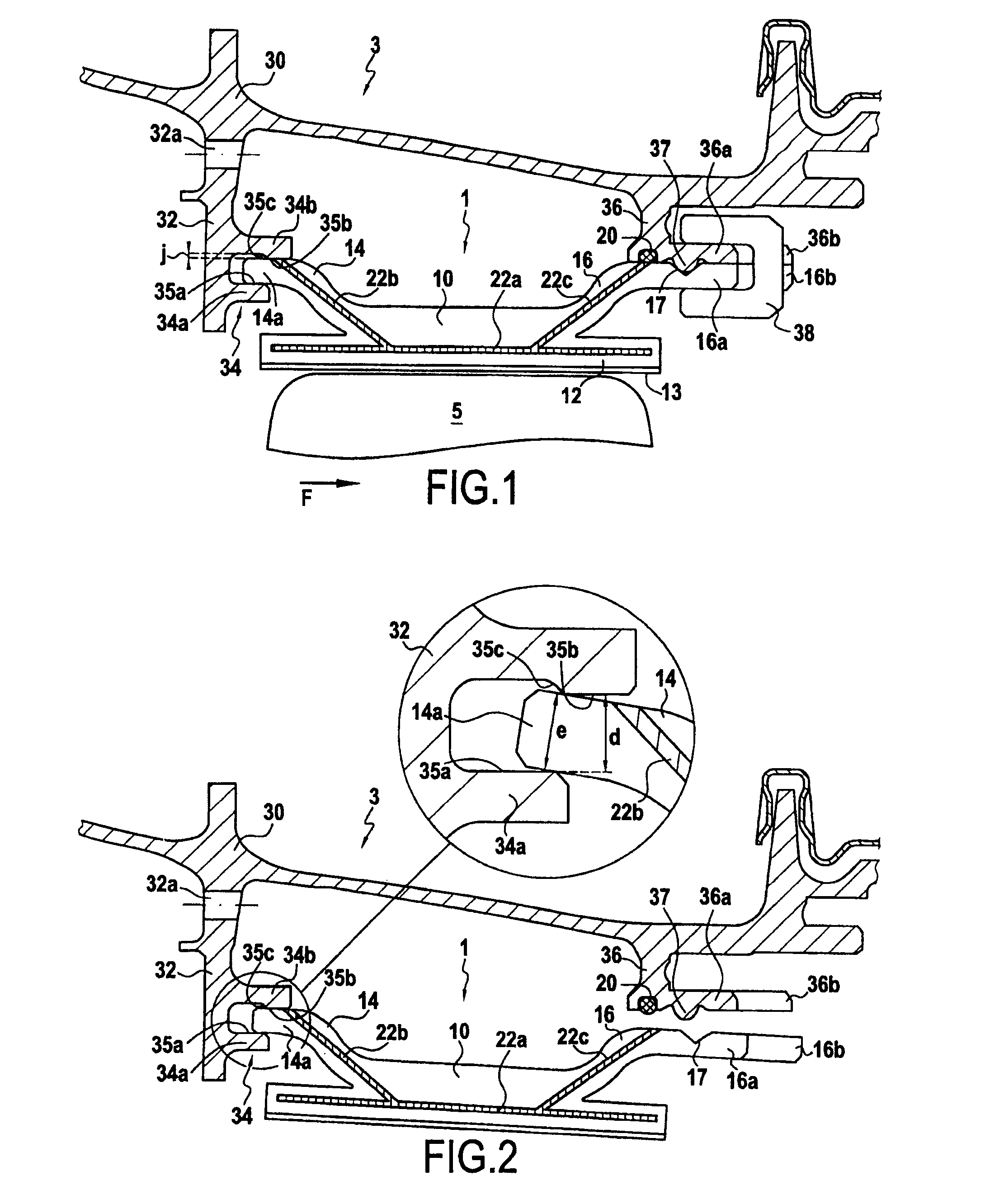
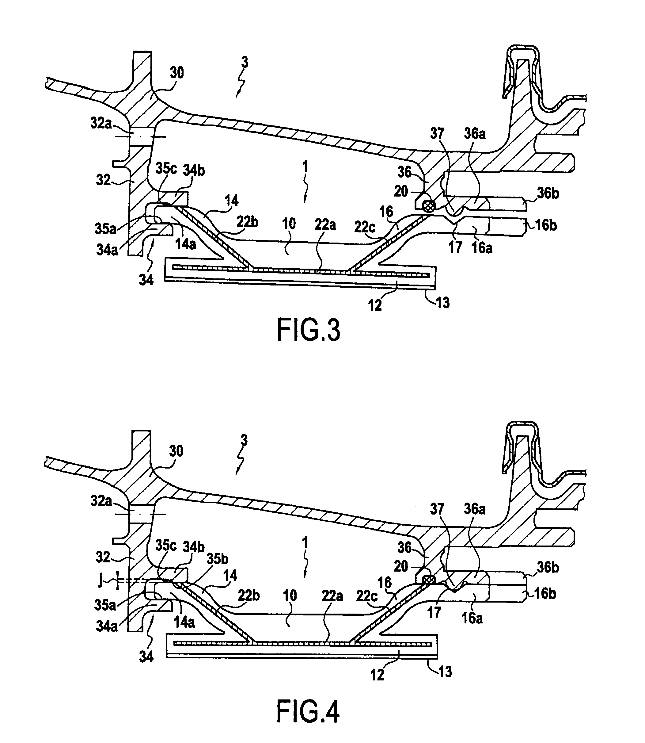
[0025]FIG. 1 shows a high-pressure turbine ring assembly comprising a CMC turbine ring 1 and a metal ring support structure 3. The turbine ring 1 surrounds a set of rotary blades 5. The turbine ring 1 is made up of a plurality of ring sectors 10, FIG. 1 being a meridian section view on a plane passing between two contiguous rings.

[0026]Each ring sector 10 has a section that is substantially π-shaped with an annular base 12 having an inside face coated in a layer 13 of abradable material defining the flow passage for the gas stream through the turbine. Tabs 14, 16 having a substantially S-shaped meridian section extend from the outside face of the annular base 12 over its entire length. One of the tabs, or upstream tab 14, extends upstream, and its upstream end portion 14a is situated upstream from the upstream end of the annular base 12. The other tab 16, or downstream tab, extends downstream and its downstream end portion 16a is situated downstream from the downstream end of the an...


PUM

PropertyMeasurementUnit
Lengthaaaaaaaaaa

Abstract

A turbine ring assembly includes a ring support structure and a plurality of ring sectors, each including a single piece of ceramic matrix composite material. Each ring sector includes a first portion forming an annular base with an inside face defining an inside face of the turbine ring and an outside face from which there extends two tab-forming portions including ends that are engaged in housings in the ring support structure. The ring sectors present a section that is substantially π-shaped and the ends of the tabs are held without radial clearance by the ring support structure. The tabs can have a free length in meridian section that is not less than three times their mean width.

Description

BACKGROUND OF THE INVENTION[0001]The invention relates to a turbine ring assembly for a turbomachine, which assembly comprises a ring support structure and a plurality of ring sectors, each comprising a single piece of ceramic matrix composite material.[0002]The field of application of the invention is particularly that of gas turbine aeroengines. Nevertheless, the invention is applicable to other turbomachines, e.g. industrial turbines.[0003]Ceramic matrix composite (CMC) materials are known for their good mechanical properties, which make them suitable for constituting structural elements, and for their capacity to conserve those properties at high temperatures.[0004]In gas turbine aeroengines, improving efficiency and reducing polluting emissions are leading pursuit of ever-higher operating temperatures.[0005]Thus, the use of CMCs for various hot portions of such engines has already been envisaged, particularly since CMCs present density that is less than that of the refractory m...

Claims


Application Information

Patent Timeline
IPC IPC(8): F01D25/24
CPCF01D9/04F01D11/08F01D25/246Y02T50/67F05D2300/603F05D2240/11F05D2260/30F05D2300/21F05D2230/642Y02T50/672D03D25/005Y02T50/60
Inventor DENECE, FRANCK ROGER DENISGENDRAUD, ALAIN DOMINIQUEHABAROU, GEORGESILLAND, HUBERTBONNEAU, DAMIEN
Owner GERAKL
Why Eureka
Try Eureka