Flywheel assembly
- Summary
- Abstract
- Description
- Claims
- Application Information
AI Technical Summary
Benefits of technology
Problems solved by technology
Method used
Image


Examples
Embodiment Construction
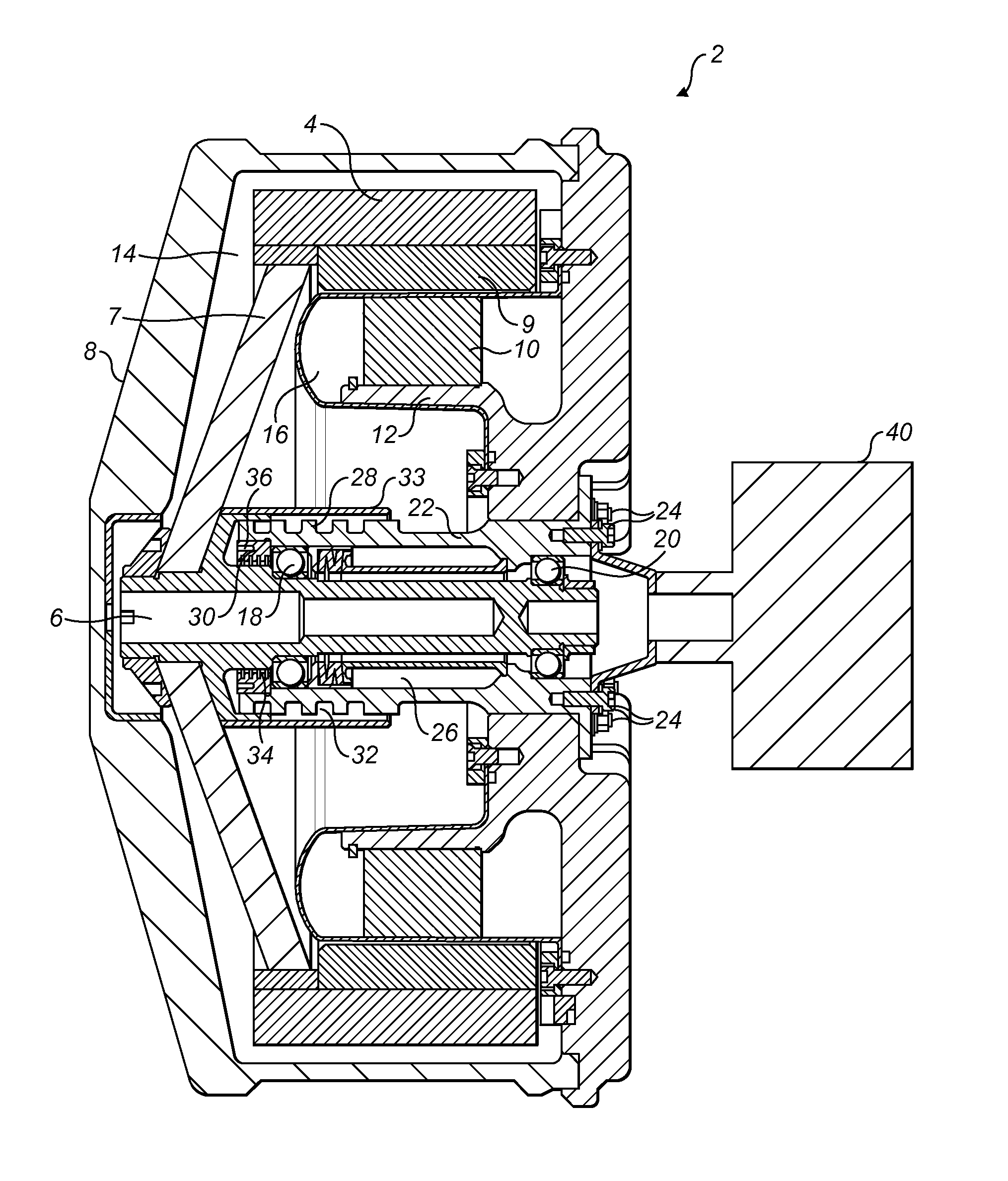
[0015]The FIGURE shows a cross-sectional side view of an electrically driven flywheel assembly 2. A carbon fibre flywheel 4 is mounted on a central shaft 6 via a composite end cap 7 and enclosed within a housing 8. Permanent magnets 9 are carried on the inner circumferential surface of the flywheel and form the rotor of a brushless DC motor.
[0016]The motor stator 10 is carried by a stator mount 12 which extends inwardly from the housing. It may have a known laminated construction, with three phase coil windings (not shown). The stator is oil cooled.
[0017]The flywheel rotates in a first chamber 14 which is defined within the housing and contains a partial vacuum. The stator is separated from the first chamber by a glass fibre can 16. The shaft 6 is rotatably supported by first and second bearings 18, 20. Each bearing comprises a plurality of ball bearings held between an inner race mounted on the shaft and an outer race supported on an inner surface of a cylindrical hub 22. Single be...
PUM
 Abstract
Description
Claims
Application Information
 - Generate Ideas
- Intellectual Property
- Life Sciences
- Materials
- Tech Scout
- Unparalleled Data Quality
- Higher Quality Content
- 60% Fewer Hallucinations
Browse by: Latest US Patents, China's latest patents, Technical Efficacy Thesaurus, Application Domain, Technology Topic, Popular Technical Reports.
© 2025 PatSnap. All rights reserved.Legal|Privacy policy|Modern Slavery Act Transparency Statement|Sitemap|About US| Contact US: help@patsnap.com