Multi-attach reusable tag

a tag and multi-attach technology, applied in the field of multi-attach reusable tags, can solve the problems of not being visually deterring, not being secured, and not being able to meet the requirements of use, and achieve the effects of facilitating reducing manufacturing and inventory costs, facilitating use flexibility, and low cos

Inactive Publication Date: 2012-02-09
CHECKPOINT SYST INC
View PDF13 Cites 14 Cited by
  • Summary
  • Abstract
  • Description
  • Claims
  • Application Information

AI Technical Summary

Benefits of technology

[0016]One of the key features of the present invention is to allow the flexibility of using one housing with multiple attachment methods by just using a different low cost attachment clip. This facilitates reducing manufacturing and inventory costs also by mass producing the high cost item (i.e., the housing) while maintaining an inventory of the low cost attachment clip.

Problems solved by technology

There are also significant legal liabilities if a broken needle leaves the factory.
Conventional security tags such as EAS hang tags, sewn-in woven tags, and drop-in-pocket tags are non-ferrous, light weight, low cost, and deactivatable, but they are not visually-deterring and cannot be secured (at least in part) prior to harsh manufacturing conditions (e.g., stone-washing of jeans).
Furthermore, EAS hang tags attached by a plastic strap and un-attached drop-in-pocket tags can easily be removed and are not secure.
Magnetic hard tags are visually deterring and secure (by a metal pin), but they are not non-ferrous, light weight, low cost, deactivatable, or capable of being secured prior to harsh manufacturing conditions.
Further, the weight of the tag may distort or wrinkle the fabric when the apparel is positioned on the hanger, the mannequin, or other display.
Thus, these types of goods do not favor the known security devices and methods for attaching such devices due to the size of the goods or the invasive nature of the products known in the art.
But as discussed above, sewn-in woven tags are not visually-deterring and cannot be secured (at least in part) prior to harsh manufacturing conditions.
Moreover, where RFID security devices are used, many people have an apprehension with such devices when they are used in connection with personal items because it harbors connotations of invasion of privacy.
Where such security devices are sewn into apparel, people are reluctant to purchase apparel that may permanently contain a device that may store information and which cannot be removed without damaging the apparel.
As a result, this security tag cannot undergo harsh manufacturing conditions.
In addition, this security tag does not utilize a deactivatable security element.
In particular, A Ser. No. 12 / 482,934 discloses a non-ferrous, light weight, low cost, secure, and visually-deterring tag; however, this tag is not deactivatable and cannot undergo harsh manufacturing conditions.

Method used


Image

  • Multi-attach reusable tag
  • Multi-attach reusable tag
  • Multi-attach reusable tag

Examples


second embodiment

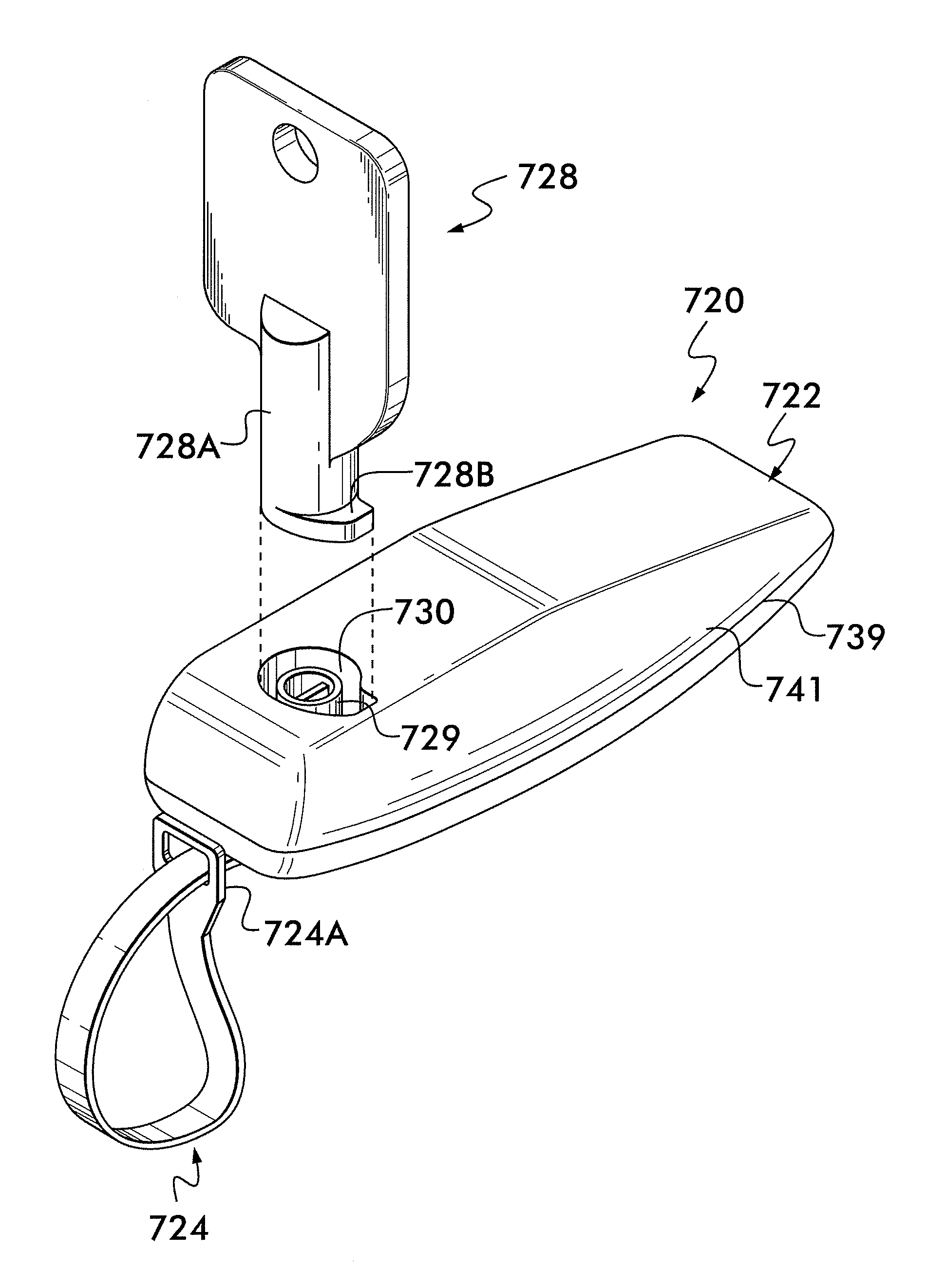
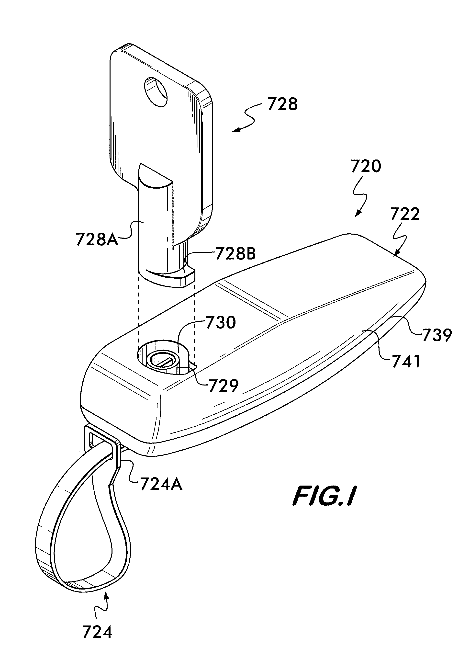
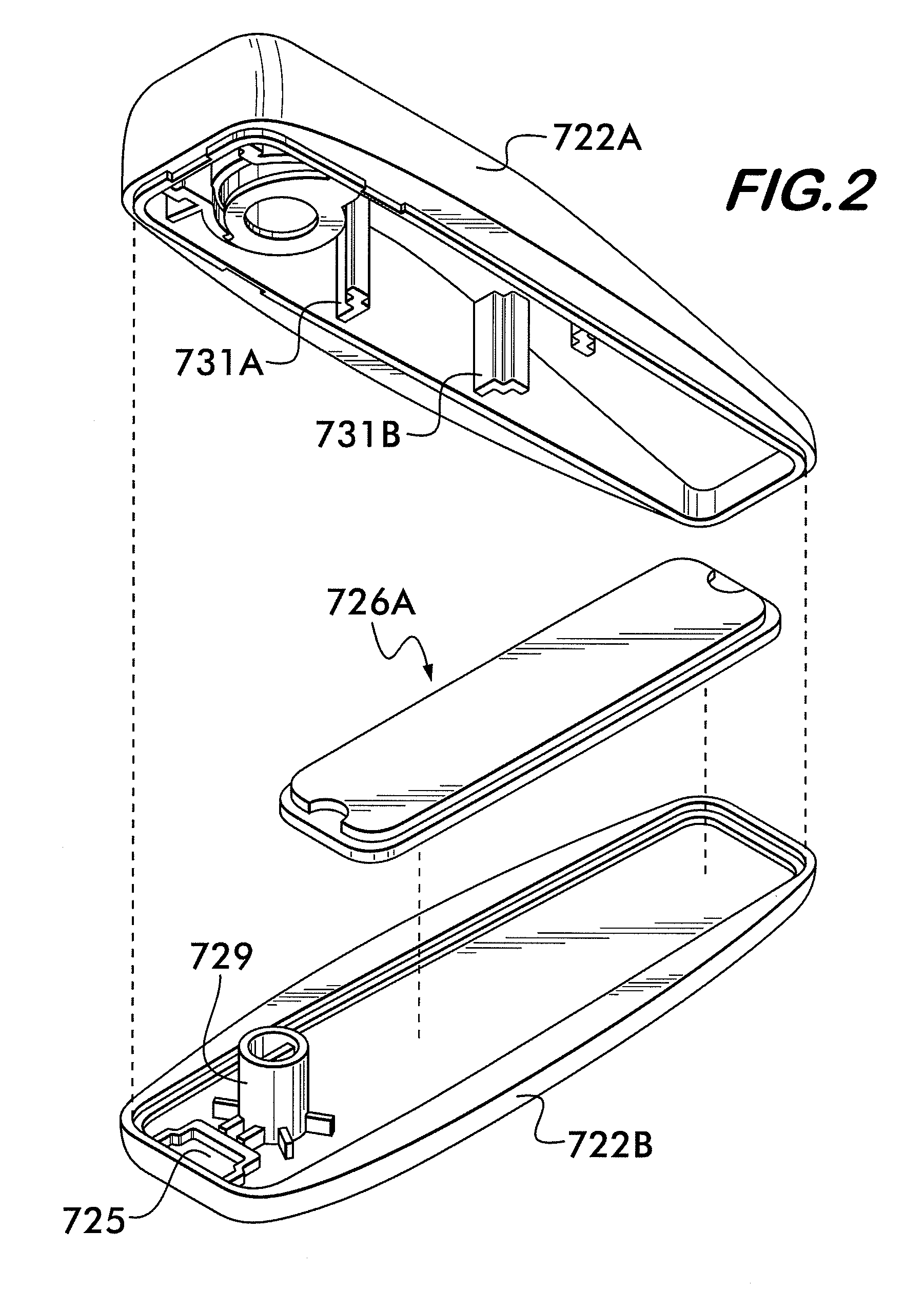
[0061]A second embodiment 920 of the MARST is shown in FIGS. 10-19 which includes a pair of apertures 725A and 725B (FIGS. 12-14) for accommodating one or two ends of an attachment clip while showing its exemplary use with a belt, shown partially. Again, the security element that may be contained therein imposes no limitation on the invention and may include, by way of example only, an AM element 726A (FIGS. 13, 15-16 and 19) or a ferrite core element 726B (FIG. 14). The second embodiment housing 922 also comprises two portions 922A and 922B, as shown most clearly in FIG. 13, which are also fixedly secured (e.g., ultrasonically welded) together.

[0062]Use of the second embodiment 920 with a belt article requires the use of only aperture 725A because the attachment clip 1024 includes the sole fluke 724B (e.g., FIG. 12). In contrast, as will be discussed later, the second embodiment 920 may be used with a different attachment clip 1124 (FIGS. 18-19) wherein both ends of the attachment ...

first embodiment

[0064]As mentioned previously, FIGS. 10-17 show the second embodiment 920 using the attachment clip 1024. This attachment clip 1024 is designed for use with belt articles 10 and in particular, the buckle portion 12 of the belt 10. Use of this attachment clip 1024 with the second embodiment 920 provides for a uniform presentation of belt merchandise with a security tag as shown in FIG. 10 where the belt products with their respective security tags are shown mounted on a store display rack prong 14. In particular, the attachment clip 1024 comprises a first hanging aperture 1024A, a second aperture 1024B, the fluke 724B, a third aperture 1024C and a body 1024D. The third aperture 1024C is positioned approximately in the center of the body 1024D. To use this attachment clip 1024, as shown most clearly in FIG. 13 or 14, the user first passes one of end of the attachment clip 1024 through the buckle portion 12 and then inserts the prong 16 portion of the belt 10 through the third aperture...


PUM


Abstract

A multi-attach reusable security tag (MARST) that is attached to an article in two stages. In a first stage, an attachment clip is coupled to an article, such as but not limited to clothing, to be protected by a manufacturer or assembler. This attachment clip is durable to withstand harsh manufacturing environments. Once the article with the attachment clip is ready for presentation, for example, at a retail establishment, during a second stage, the attachment clip is then secured in a releasable locking mechanism of a housing containing a security element therein. The security element may comprise EAS (including AM, RF, EM and microwave), RFID (including LF, HF and UHF) elements or any combination thereof. Alternatively, a fluke element can be used to secure the attachment clip to the releasable locking mechanism and wherein this fluke element permits the attachment clip to swivel outside of the housing. A preferred embodiment of the security tag uses all non-ferrous components including its locking mechanism. Thus, the security tags combine the qualities of being non-ferrous, light-weight, low cost, deactivatable, secure, visually-deterring, and installable in two stages to the article it is meant to protect.

Description

CROSS-REFERENCE TO RELATED APPLICATIONS[0001]This continuation-in-part application claims the benefit under 35 U.S.C. §120 of application Ser. No. 12 / 887,229 filed on Sep. 21, 2010 entitled TWO-STAGE UNIVERSAL SECURITY HARD TAG AND METHOD FOR ATTACHING AND DETACHING which in turn is a continuation-in-part application which claims the benefit under 35 U.S.C. §120 of application Ser. No. 12 / 482,934 filed on Jun. 11, 2009 entitled SECURITY HARD TAG WITH ATTACHMENT CLIP AND METHOD FOR ATTACHING AND DETACHING which, in turn, claims the benefit under 35 U.S.C. §119(e) of Provisional Application Ser. No. 61 / 157,237 filed on Mar. 4, 2009 entitled NON-FERROUS HARD TAG and of Provisional Application Ser. No. 61 / 163,677 filed on Mar. 26, 2009 also entitled NON-FERROUS HARD TAG and all of whose entire disclosures are incorporated by reference herein.BACKGROUND OF THE INVENTION[0002]1. Field of Invention[0003]The present invention generally relates to the field of security tags, and more particu...

Claims


Application Information

Patent Timeline
Patent Type & Authority Applications(United States)
IPC IPC(8): G08B13/14
CPCE05B47/0004E05B73/0064E05B73/0017Y10T70/5009Y10T70/333Y10T70/317Y10T70/5004
Inventor BRODZIK, JAMESPICCOLI, ANTHONY F.APPALUCCI, LAWRENCEMAZOKI, GARYMCKEOWN, THOMAS J.STRAUSER, SETHWEI, WU
Owner CHECKPOINT SYST INC
Why Eureka
Try Eureka