Temporary Rivet

a technology of rivets and rivet holes, applied in the field of metal rivets, can solve the problems of ringing of head materials, further progression of drills, and undesired heavy scratching of outer workpieces

Inactive Publication Date: 2012-02-09
ALLFAST FASTENING SYST
View PDF7 Cites 8 Cited by
  • Summary
  • Abstract
  • Description
  • Claims
  • Application Information

AI Technical Summary

Problems solved by technology

An alternative approach that has been used by Cherry Aerospace LLC is to use a temporary fastener head that on installation, will sit flat against the outer workpiece, though this has the disadvantage of leaving a ring of head material when the drill bit separates the head from the sleeve of the temporary fastener, which ring then spins with the drill bit to prevent further penetration thereof.
This can also result in drill bit wander, resulting in undesired heavy scratching of the outer workpiece.
Still there is the possibility that a dull but still functional drill, per...

Method used


Image

  • Temporary Rivet
  • Temporary Rivet
  • Temporary Rivet

Examples


Embodiment Construction

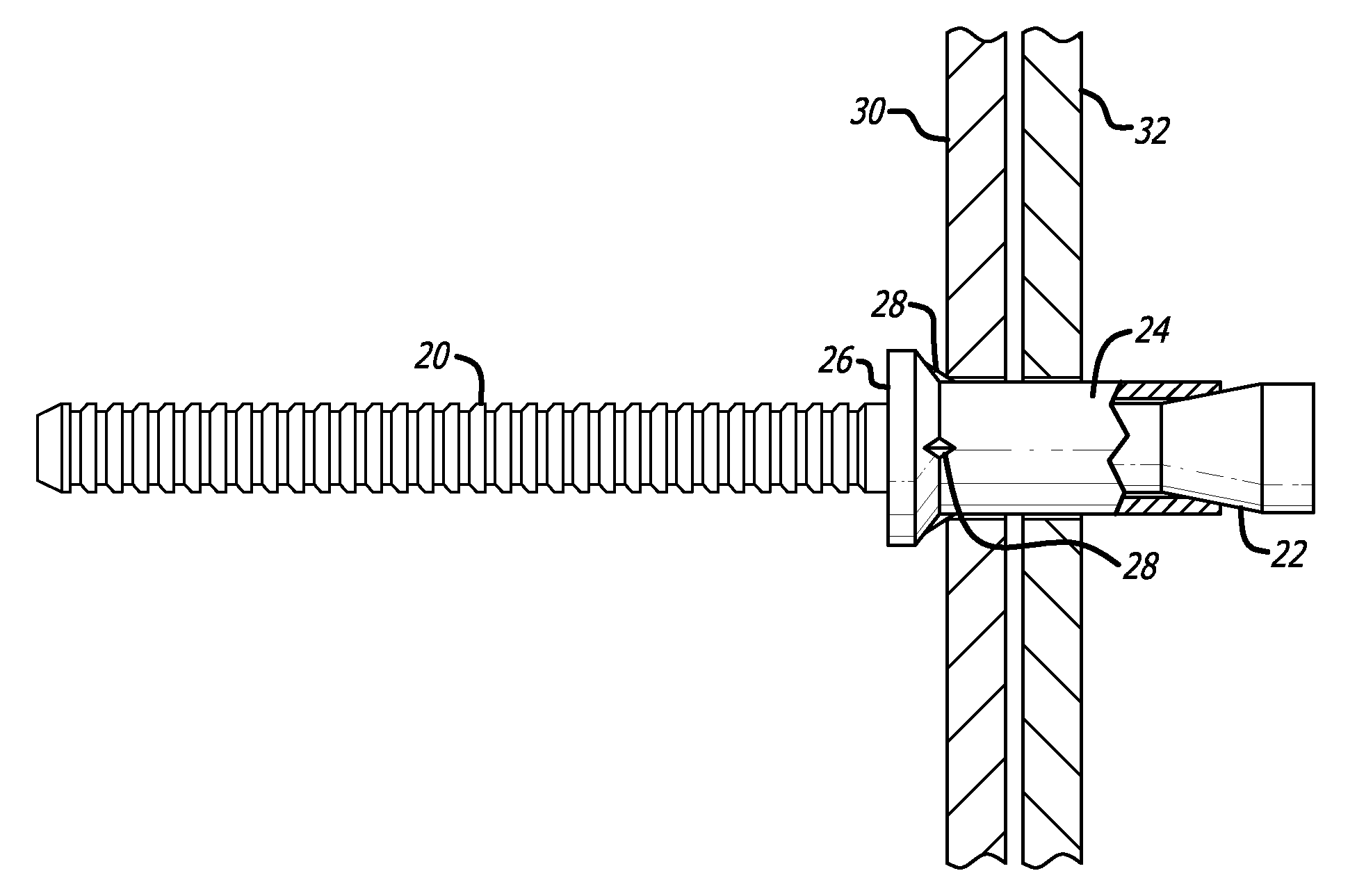
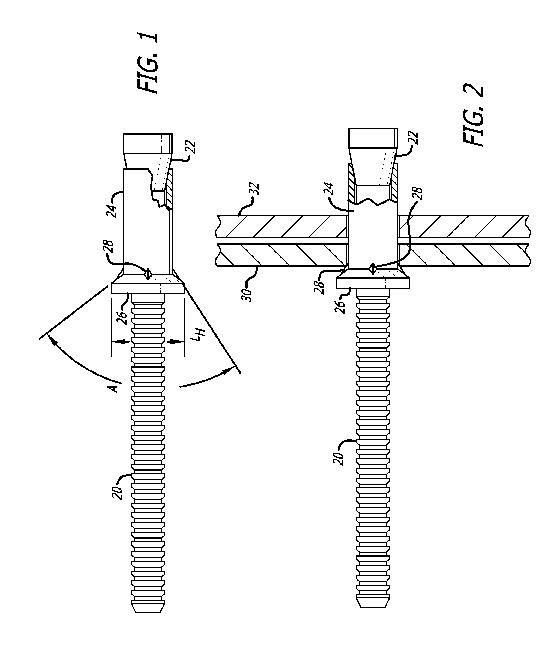
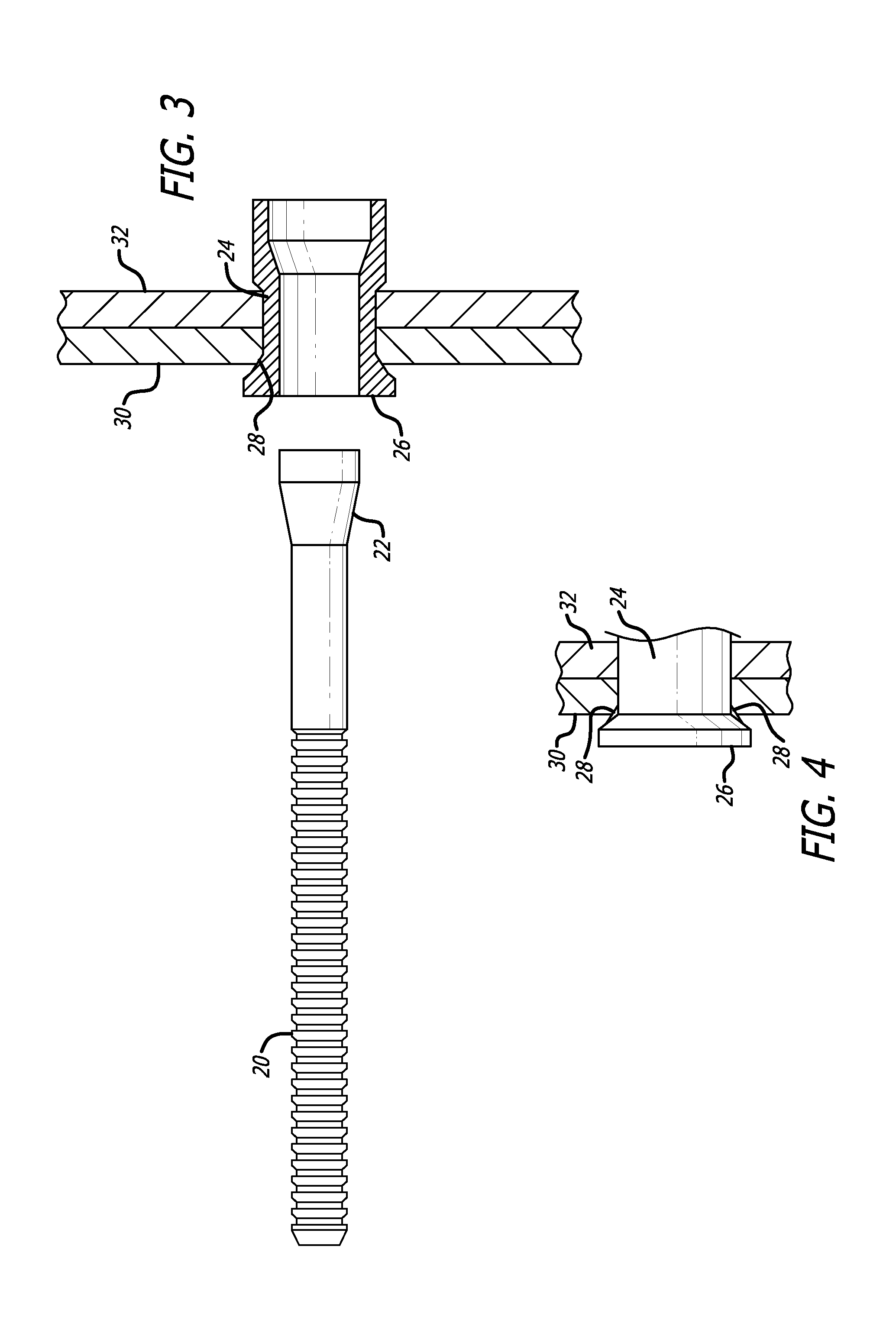
[0015]First referring to FIG. 1, a temporary rivet in accordance with a preferred embodiment of the present invention may be seen. The temporary rivet is comprised of a pulling stem 20 with a tapered and enlarged head 22 thereon, within a sleeve 24 having a head 26 thereon. The sleeve side of the head 26 is tapered at an included angle A that is purposely made smaller than the included angle on the end of the drill which will be used to later drill out the temporary rivet to form the hole for the permanent fastener (FIGS. 5 and 6). Similarly, the diameter LH of the head 26 is purposely made smaller than the diameter of the drill which will later be used to form the hole in the workpieces for the permanent fastener (FIGS. 5 and 6 again). This structure as just described is in accordance with the preferred embodiment of the prior art patent hereinbefore referred to. However, in addition, the temporary rivet of FIG. 1 includes projections or ribs 28 in the region of the intersection of...


PUM

PropertyMeasurementUnit
Angleaaaaaaaaaa
Angleaaaaaaaaaa
Electrical resistanceaaaaaaaaaa

Abstract

A temporary fastener or temporary blind rivet having a cylindrical sleeve and a sleeve head thereon, the region where the sleeve and sleeve head mate having a plurality of local protrusions thereon, with a stem passing through the sleeve head and sleeve, the stem having an enlarged stem head thereon adjacent the end of the sleeve opposite the sleeve head, the stem for pulling relative to the sleeve head to cause the enlarged stem head to form a blind side head on the sleeve, to pull the workpieces together, to cause the local protrusions to make depressions in, and to fill the depressions in, an outer edge of the hole in the adjacent workpiece, and to pull through the sleeve and sleeve head to expand the sleeve into a tight fit in the hole in the workpieces. The protrusions make indentations in the edge of the hole in the adjacent workpiece to provide increased resistance to spinning when the temporary blind rivet is drilled out for a permanent fastener.

Description

BACKGROUND OF THE INVENTION[0001]1. Field of the Invention[0002]This invention relates to the field of metal rivets, and more particularly, temporary blind rivets.[0003]2. Prior Art[0004]U.S. Reissue Pat. No. 38,664 discloses a method for creating a hole for a permanent fastener that replaces a tacking fastener (temporary rivet). The tacking fastener preferably used with respect to that method is a blind tacking fastener having a number of features, not all of which must be used to achieve at least some of the desired objectives. In particular, in a preferred form the temporary fastener has a head with an outer diameter which is less than the diameter of the drill 34 which will be used to drill out the temporary fastener and create a hole in the workpieces for a permanent fastener. This avoids having rings cut from temporary fastener heads that are larger than the shank of the permanent fastener when drilling out for the final fastener, which rings tended to build up on the drill an...

Claims


Application Information

Patent Timeline
IPC IPC(8): F16B19/04B21J15/02
CPCB21J15/043B21J15/50Y10T29/49956F16B19/109F16B19/1045
Inventor LUHM, RALPH
Owner ALLFAST FASTENING SYST
Why Eureka
Try Eureka