
Touch screen device

a touch screen and device technology, applied in the field of touch screen devices, can solve the problems of difficult application to portable devices whose size and thickness have been reduced, junction interfaces are relatively highly likely to be infiltrated, and touch screen devices b>10/b> are more frequently damaged, so as to reduce the number of junction interfaces exposed and prevent moisture or oil infiltration.

Inactive Publication Date: 2012-02-16
SAMSUNG ELECTRO MECHANICS CO LTD
View PDF2 Cites 5 Cited by
  • Summary
  • Abstract
  • Description
  • Claims
  • Application Information

AI Technical Summary

Benefits of technology

The present invention is about a touch screen device that has a high definition image for the user. It also reduces the number of interfaces exposed to the outside to prevent moisture or oil from entering the touch screen. The device includes a first transparent electrode and a second transparent electrode made of conductive polymer, which sense touch input through a change in resistance or voltage. The device also has a first adhesive layer and a second adhesive layer to bond the substrates together. The invention provides a better user experience with the touch screen device.

Problems solved by technology

These input devices, however, have been developed in consideration of the expanding usage of personal computers, such that they are difficult to be applied to portable devices that are recently reduced in size and thickness.
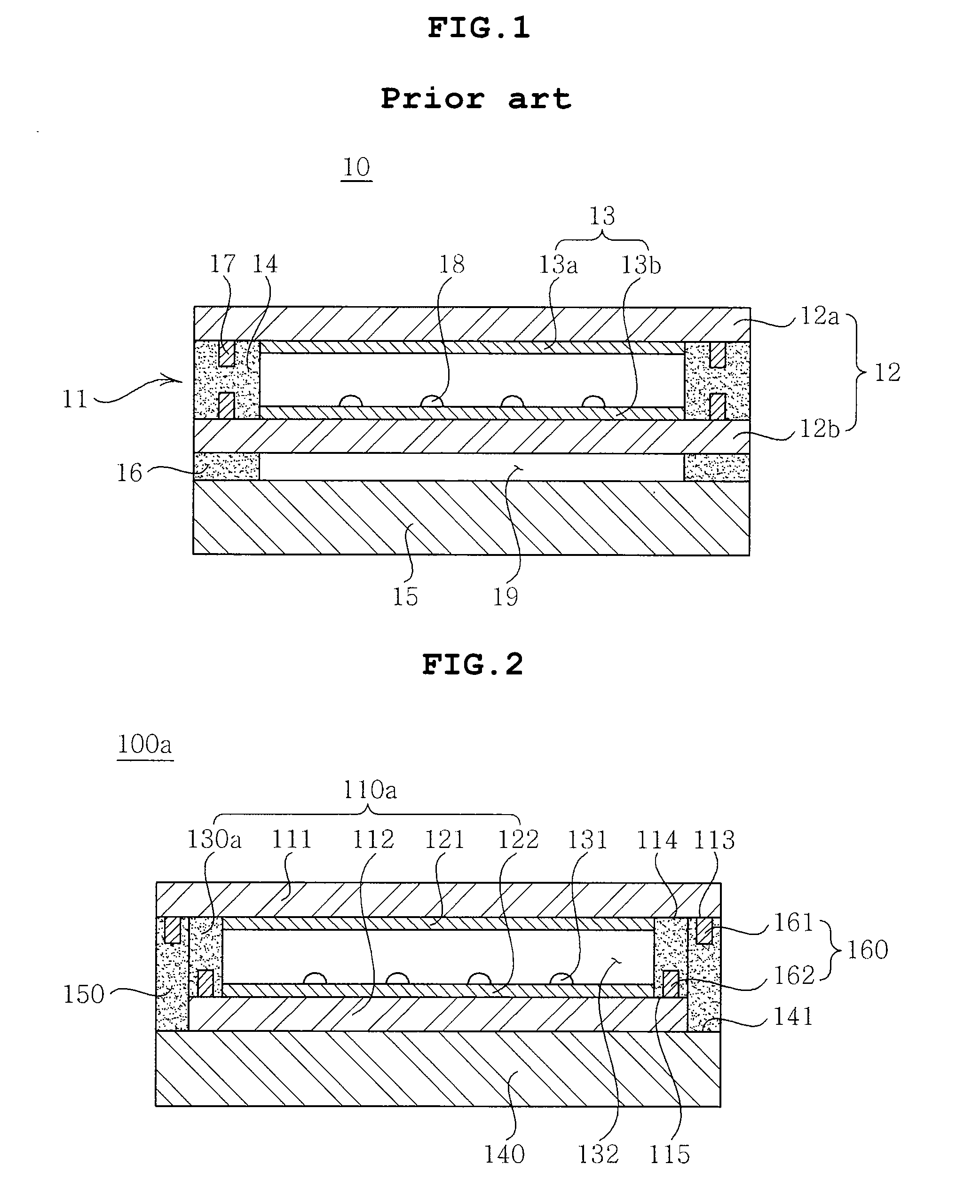
The junction interface is relatively highly likely to be infiltrated with moisture, oil or the like, such that the touch screen device 10 is more frequently damaged due to the infiltrated moisture, oil or the like.

Method used


Image

  • Touch screen device
  • Touch screen device
  • Touch screen device

Examples


first embodiment

[0031]Structure of Touch Screen—First Embodiment

[0032]FIG. 2 is a cross-sectional view of a touch screen device 100a according to a first preferred embodiment of the present invention. Hereinafter, the touch screen device 100a according to the present embodiment will be described with reference to the figure.

[0033]As shown in FIG. 2, the touch screen device 100a according to the present embodiment includes a touch screen 110a including a first transparent substrate 111, a first transparent electrode 121, a second transparent substrate 112, a second transparent electrode 122, and a first adhesive layer 130a, a display 140, and a second adhesive layer 150 bonding the touch screen 110a to a display 140.

[0034]Herein, the present embodiment will describe a case in which the touch screen 110a is a resistive type.

[0035]The first transparent substrate 111, which is a member receiving a touched input from a specific object such as a user's body, a stylus pen or the like, provides a space for...

second embodiment

[0062]Structure of Touch Screen—Second Embodiment

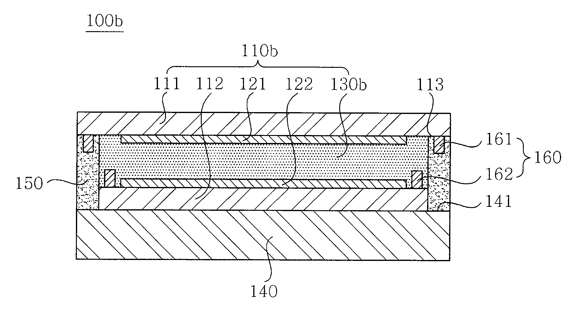
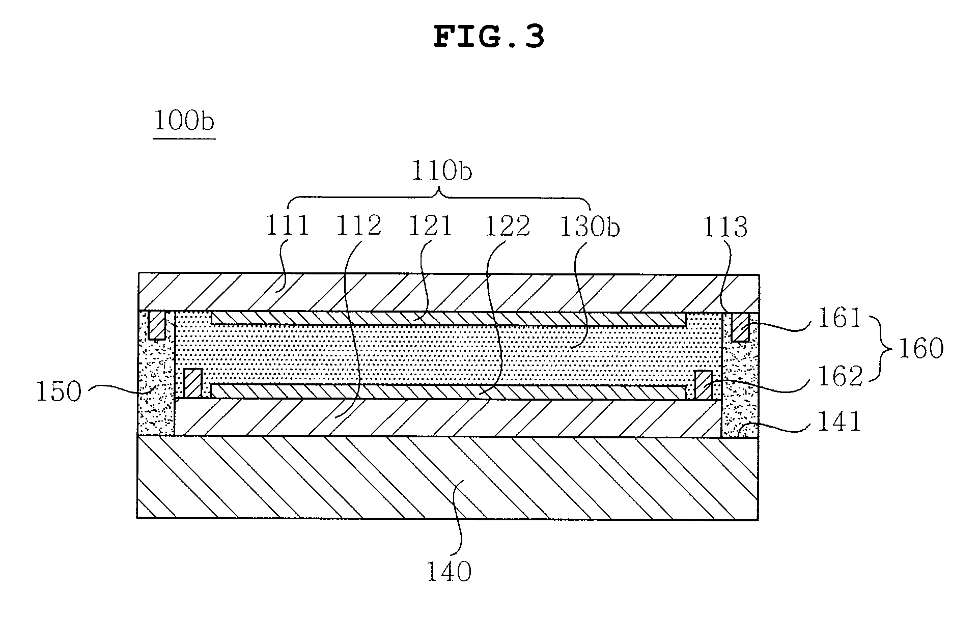
[0063]FIG. 3 is a cross-sectional view of a touch screen device 100b according to a second preferred embodiment of the present invention. Hereinafter, the touch screen device 100b according to the present embodiment will be described with reference to the figure. Herein, like reference numerals will designate like or corresponding components and the description overlapping with the first embodiment will be omitted.

[0064]As shown in FIG. 3, the touch screen device 100b according to the present embodiment includes a touch screen 110b including a first transparent substrate 111, a first transparent electrode 121, a second transparent substrate 112, a second transparent electrode 122, and a first adhesive layer 130b, a display 140, and a second adhesive layer 150 bonding the touch screen 110b to a display 140.

[0065]Herein, the present embodiment will describe a case in which the touch screen 110b is a capacitive type.

[0066]The first trans...


PUM


Abstract

Disclosed herein is a touch screen device, including: a first transparent electrode formed on one surface of a first transparent substrate to sense a touched input; a second transparent electrode formed on one surface of a second transparent substrate formed to be opposite to the first transparent electrode to sense a touched input; a display formed on the other surface of the second transparent substrate; a first adhesive layer bonding the first transparent substrate to the second transparent substrate; and a second adhesive layer bonding a first connection part formed on an outer side of first transparent substrate to a second connection part formed on an outer side of the display. The touch screen device directly bonds the first transparent substrate to the display, thereby making it possible to provide a high definition image to a user and to reduce infiltration of moisture or the like.

Description

CROSS REFERENCE TO RELATED APPLICATION[0001]This application claims the benefit of Korean Patent Application No. 10-2010-0077480, filed on Aug. 11, 2010, entitled “Touch Screen Device”, which is hereby incorporated by reference in its entirety into this application.BACKGROUND OF THE INVENTION[0002]1. Technical Field[0003]The present invention relates to a touch screen device.[0004]2. Description of the Related Art[0005]With the continuous development in the electronic technology and the information technology fields, the relative importance of electronic devices is constantly increasing in everyday life, including work environment. In particular, as electronic technology continuously develops, personal computers, portable transmitters etc. process texts and graphics, using a variety of input devices, such as a keyboard, a mouse, a digitizer, etc. These input devices, however, have been developed in consideration of the expanding usage of personal computers, such that they are diffic...

Claims


Application Information

Patent Timeline
Patent Type & Authority Applications(United States)
IPC IPC(8): G06F3/042
CPCG06F3/044G06F3/045G06F3/0445
Inventor KIM, WOON CHUNOH, YONG SOOKIM, HYUN JUNLEE, JONG YOUNG
Owner SAMSUNG ELECTRO MECHANICS CO LTD
Learn More