Kinetic dumbbell

a kinetic and dumbbell technology, applied in the field of training apparatus, can solve the problems of counterweights and springs in the handle going off, user may lose interest in using the dumbbell, and counterweights may hurt someon

Inactive Publication Date: 2012-02-16
UCHEER HEALTH TECH
View PDF12 Cites 11 Cited by
  • Summary
  • Abstract
  • Description
  • Claims
  • Application Information

AI Technical Summary

Benefits of technology

[0007]The primary objective of the present invention is to provide

Problems solved by technology

Besides, conventional dumbbells are used for arm training only that user may lose interest in using the dumbbells soon after some time of use.
However, when the counterweights are reciprocating, they impact the lids on opposite sides of the handle and mak

Method used


Image

  • Kinetic dumbbell
  • Kinetic dumbbell
  • Kinetic dumbbell

Examples


Embodiment Construction

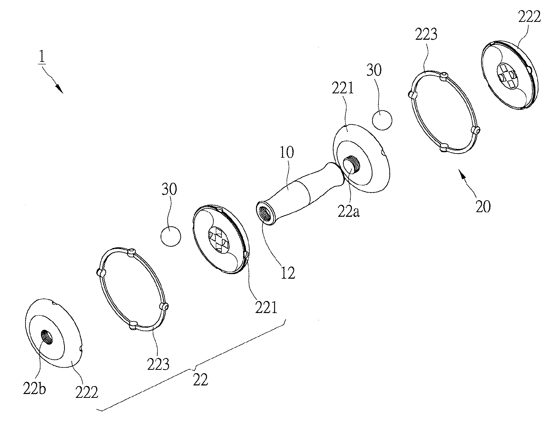
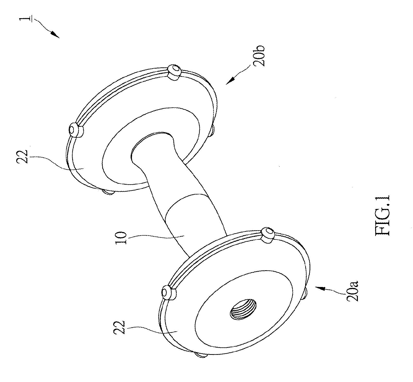
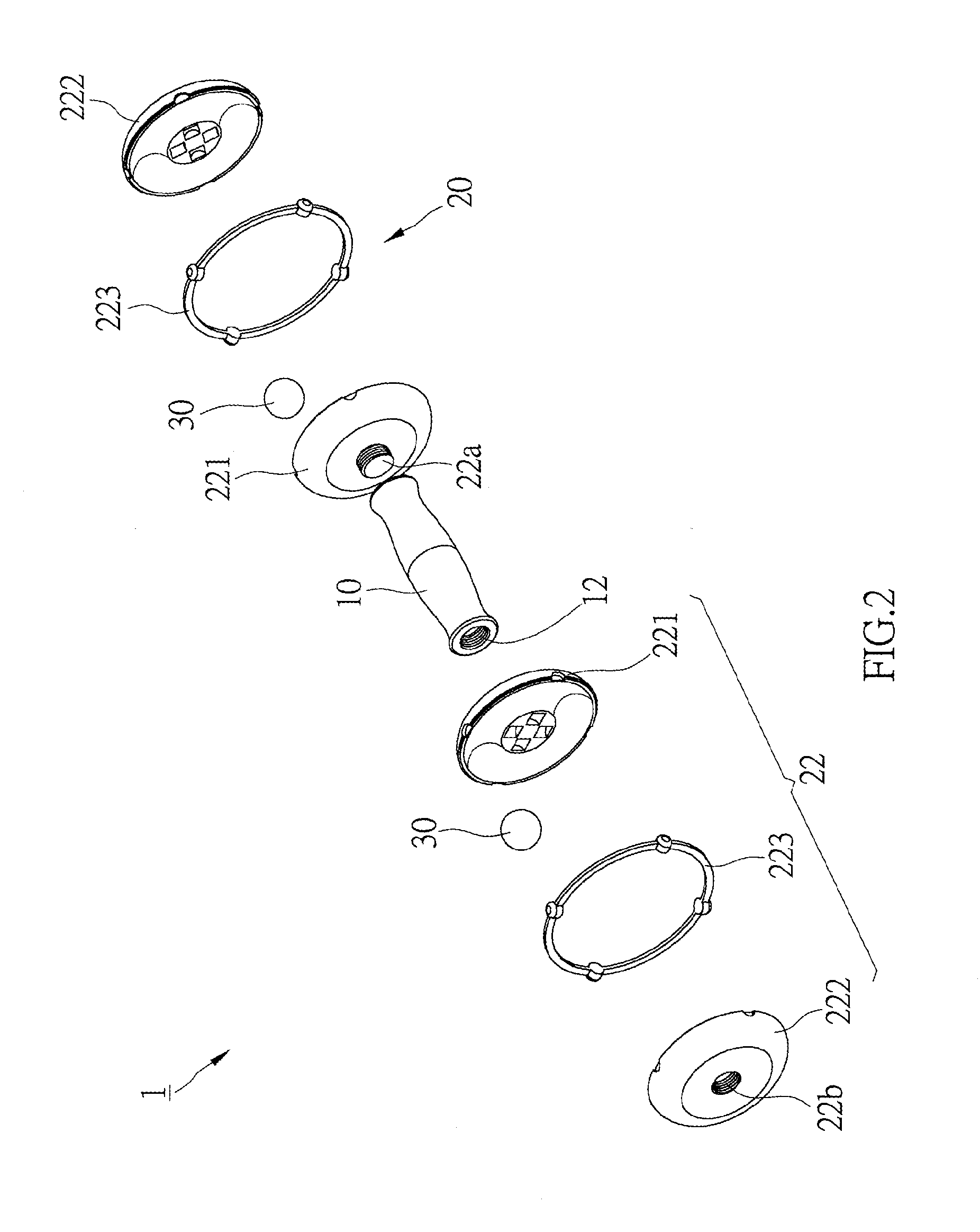
[0023]As shown in FIG. 1 and FIG. 2, a kinetic dumbbell 1 of the first preferred embodiment of the present invention includes a handle 10, two weight devices 20 and a rolling device 30.

[0024]The handle 10 is a bar having two connecting portions 12 at opposite ends. In the present embodiment, the connecting portions 12 have threaded holes. The handle 10 has a curved surface that user may hold the handle 10 firmly while training.

[0025]The weight devices 20, including a first weight device 20a and a second weight device 20b, are connected to the opposite ends of the handle 10. Each weight devices 20a, 20b has a first kinetic member 22. The first kinetic member 22 has a first case 221, a second case 222 and a rubber pad 223. As shown in FIG. 3 and FIG. 4, the first and second cases 221, 222 are connected together to form an annular channel S1 therein. A center axis LC1 of the annular channel S1 and an axis L1 of the handle are at the same line.

[0026]The first case 221 has a connecting p...


PUM


Abstract

A kinetic dumbbell of the present invention includes a handle and two weight devices connected to opposite ends of the handle. Each of the weight devices has an annular channel and at least a ball received in the annular channel. The balls are running in the endless annular channels to provide an extra vibration effect while training with the kinetic dumbbell of the present invention.

Description

BACKGROUND OF THE INVENTION[0001]1. Field of the Invention[0002]The present invention relates generally to a training apparatus, and more particularly to a kinetic dumbbell.[0003]2. Description of the Related Art[0004]Conventional dumbbells for training usually are a single element with a constant weight. User has to buy many dumbbells of different weights for different trainings. Besides, conventional dumbbells are used for arm training only that user may lose interest in using the dumbbells soon after some time of use.[0005]To overcome the drawbacks above, a swing-type dumbbell which provides an extra vibration effect in training is presented in the market. Such dumbbell, as taught in Taiwan Utility Model Patent No. M376318, includes a tubular handle, some counterweights and springs received in the handle, and two lids closing opposite ends of the handle. The counterweights are reciprocating in the handle to compress the springs to provide vibration effect when user holds and move...

Claims


Application Information

Patent Timeline
IPC IPC(8): A63B21/22
CPCA63B21/0608A63B21/0726A63B21/22A63B21/075A63B21/0728A63B21/0004A63B21/00065
Inventor CHEN, LARRY
Owner UCHEER HEALTH TECH
Why Eureka
Try Eureka