Regulatuble fastening mould cotton core shoping hub

A cotton core and button mold technology, applied in clothing, underwear, baby underwear, etc., can solve the problems of fixed mold cavity and inability to adjust the thickness of the cotton core, so as to achieve beautiful appearance, save waste suction fan and cutter assembly, and facilitate the the effect of making

Active Publication Date: 2005-06-08
ANQING HENG CHANG MACHINERY
View PDF0 Cites 12 Cited by
  • Summary
  • Abstract
  • Description
  • Claims
  • Application Information

AI Technical Summary

Problems solved by technology

For buckle molding, the problem is that the mold cavity is fixed, and the thickness of the cotton core cannot be adjusted.

Method used


Image

  • Regulatuble fastening mould cotton core shoping hub
  • Regulatuble fastening mould cotton core shoping hub
  • Regulatuble fastening mould cotton core shoping hub

Examples


Embodiment

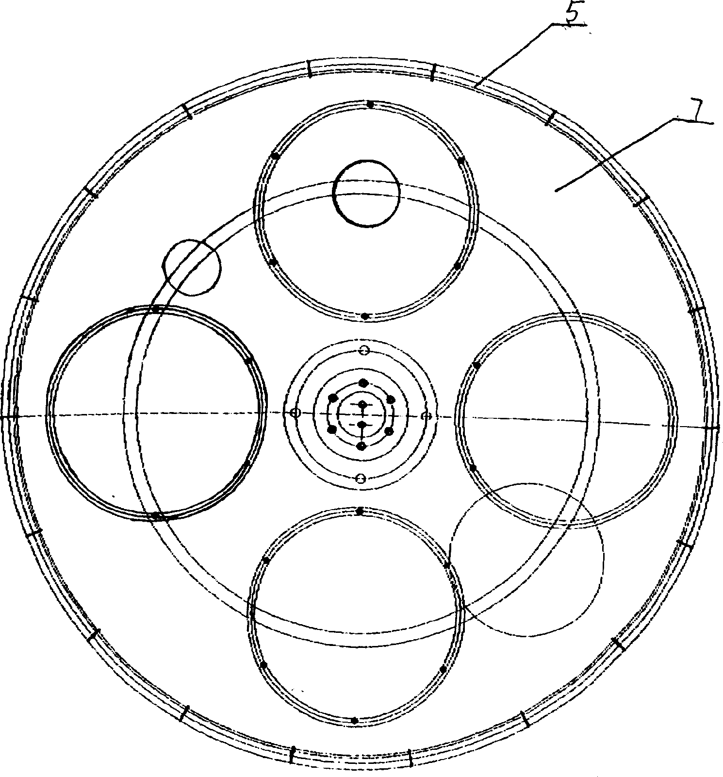
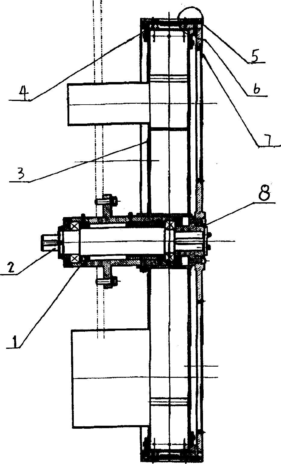
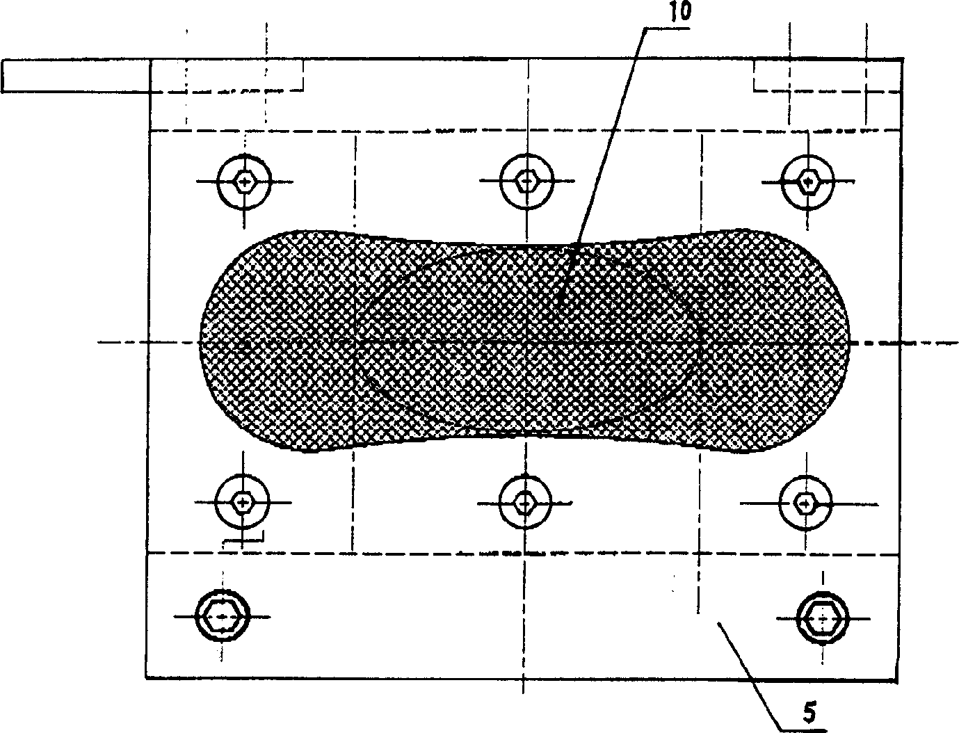
[0025] See figure 1 , figure 2 , The adjustable buckle mold cotton core forming hub includes a main shaft 2, a bearing seat 1, a negative pressure cylinder 3, a pressure ring 4, a tire mold module 5, a sealing ring 6, a turntable 7, a fixed disk 8 and a seal 9. The tire mold module 5 includes tire mold fixing tiles 12 , tire mold steel wire mesh 10 , tire mold pressing plate 14 and tire mold connecting plate 13 . Tire mold is fixed. 12 and the tire mold steel wire mesh 10 flange between tire mold pressure plate 14 are equipped with tire mold gasket 11, the middle part of the tire mold gasket is an opening, and the hole is connected with the middle part of the tire mold steel wire mesh. The groove corresponds to see in Image 6 , Figure 7 , Figure 8 and Figure 9 .

[0026] The tire mold spacer 11 is either installed on one side adjacent to the tire mold pressure plate 14, or installed on one side adjacent to the tire mold fixed tile 12.

[0027] When it is necessary ...


PUM


Abstract

An adjustable cotton core shaping die set for the sanitary napkin using the wool pulp as its absorbing body features that the cushion pad of die is arranged at the cupred edge position of the steel wire mesh between the die fixing block and the die pressing plate. Regulating the depth of die cavity can regulate the thickness of cotton core.

Description

technical field [0001] The invention relates to a forming device for a sanitary napkin using fluff pulp as an absorber. Background technique [0002] In the production line of sanitary napkins with fluff pulp as the absorbent body, there are two methods for forming the intermediate absorbent body. One is to wrap the fluff pulp with toilet paper and cut it with an inner cutter to become an intermediate absorbent body, which is commonly referred to as continuous absorbent. Paper-wrapped cotton forming; the other is to absorb the fluff pulp in the mold cavity of the forming hub without using toilet paper, which is commonly referred to as buckle molding. [0003] Both types of molding are completed on the forming hub. The continuous cotton absorbent body has a continuous concave mold on the peripheral surface of the forming hub. The buckle-molded absorber has uniformly distributed discontinuous die cavities on the peripheral surface of the forming hub. For button molding, the ...

Claims


Application Information

Patent Timeline
Patent Type & Authority Applications(China)
IPC IPC(8): A61F13/15
Inventor 吕兆荣曹新贵
Owner ANQING HENG CHANG MACHINERY
Why Eureka
Try Eureka