
Variable offset spine fixation system and method

a fixation system and variable offset technology, applied in the field of variable offset spine fixation system and method, can solve the problems of incross-threading of locking screw, difficult seating of rod and insertion of multiple locking caps, and inconvenient insertion of rod into anchoring

Inactive Publication Date: 2012-02-16
DEPUY SYNTHES PROD INC
View PDF0 Cites 68 Cited by
  • Summary
  • Abstract
  • Description
  • Claims
  • Application Information

AI Technical Summary

Problems solved by technology

Seating of the rod and insertion of the multiple locking caps can be challenging due to the anatomical placement of the bone anchors, the nature of the anatomical correction required, less than optimal rod bending, and other factors that can complicate the reduction of the rod into the anchor seats.
Complicated rod reduction may result incross-threading of the locking screw, anchor seat damage and potential replacement of the pedicle screw and anchor seat assembly mid-surgery.
Preassembled screw and anchor seat assemblies have a profile that reduces the surgeon's visibility during its implantation and, further, its footprint, once implanted, decreases the amount of working space available in the anatomy.
Surgeons often struggle to achieve full rod reduction or anatomical correction even using bottom-loading, pop-on head type pedicle screw systems.
While powerful rod reduction instruments are available for use with the rod and screw construct systems, the surgeon is often not able to completely reduce the rod into the anchor seat without pre-bending and re-bending the rod to the point at which the rod may become weakened.
Further, the application of too much force during the reduction of the spinal rod may also cause one or more of the implanted bone anchors to be dislodged from the vertebral bodies in which they are implanted.

Method used


Image

  • Variable offset spine fixation system and method
  • Variable offset spine fixation system and method
  • Variable offset spine fixation system and method

Examples


Embodiment Construction

[0014]Certain terminology is used in the following description for convenience only and is not limiting. The words “right”, “left”, “lower” and “upper” designate directions in the drawings to which reference is made. The words “inwardly” or “distally” and “outwardly” or “proximally” refer to directions toward and away from, respectively, the geometric center of the spine fixation system and related parts thereof. The words, “anterior”, “posterior”, “superior,”“inferior” and related words and / or phrases designate preferred positions and orientations in the human body to which reference is made and are not meant to be limiting. The terminology includes the above-listed words, derivatives thereof and words of similar import.

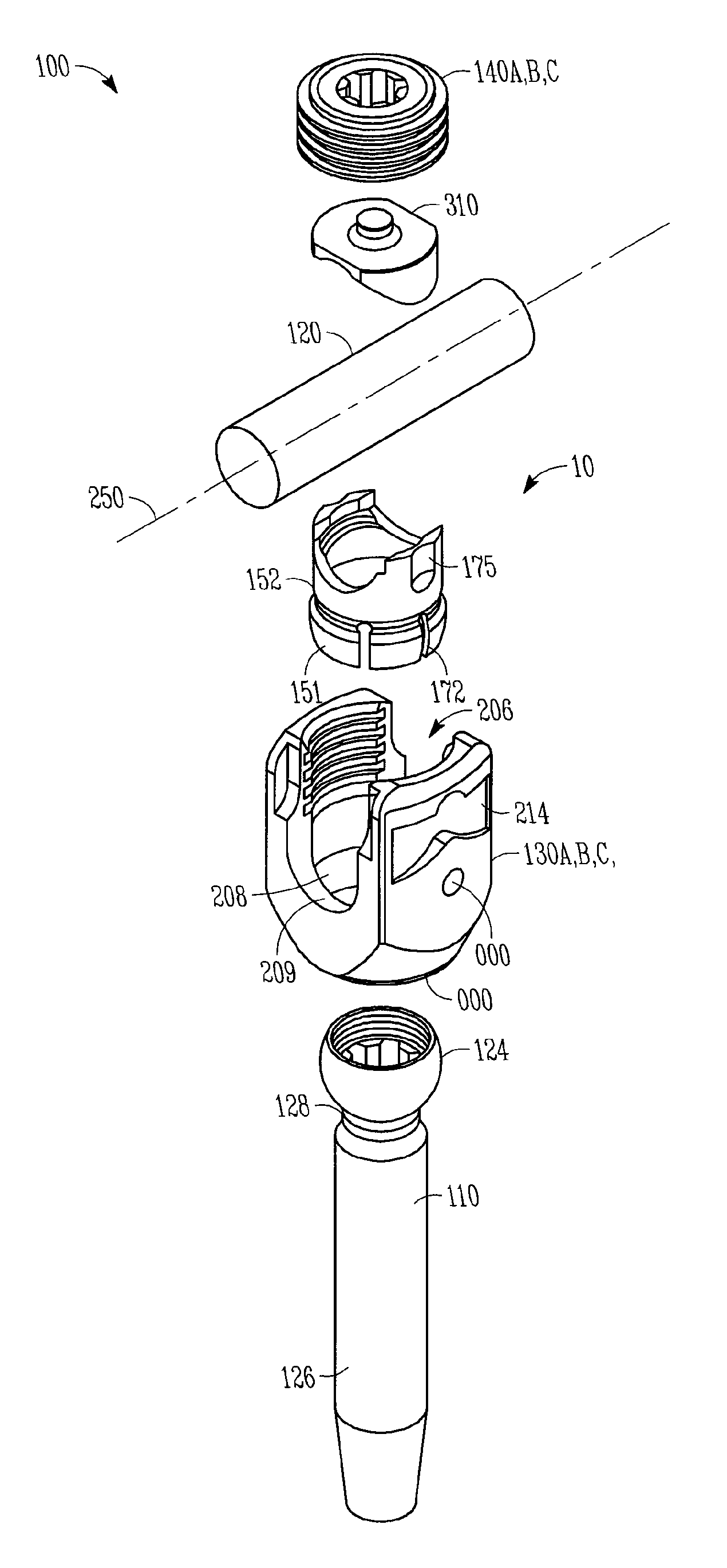
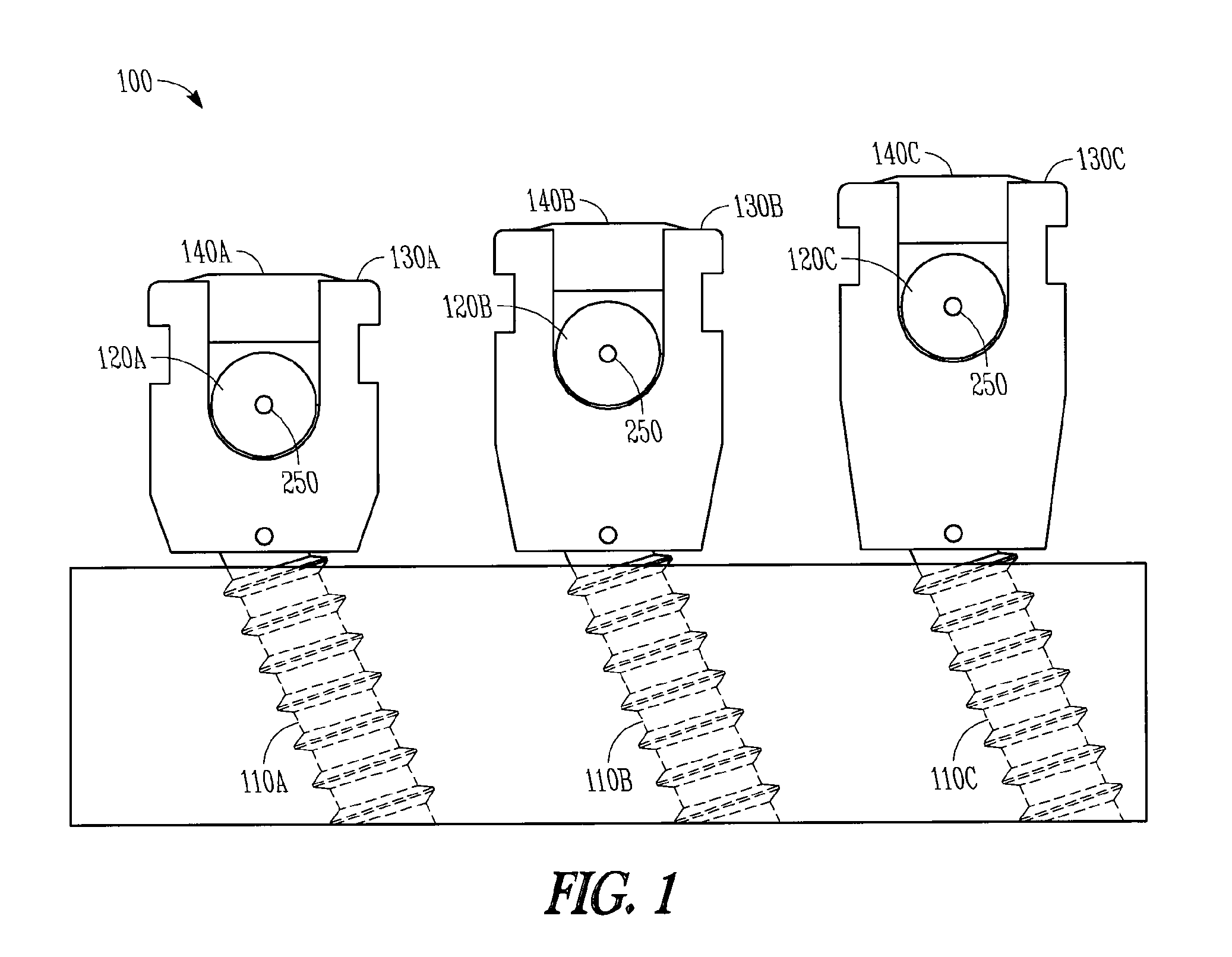
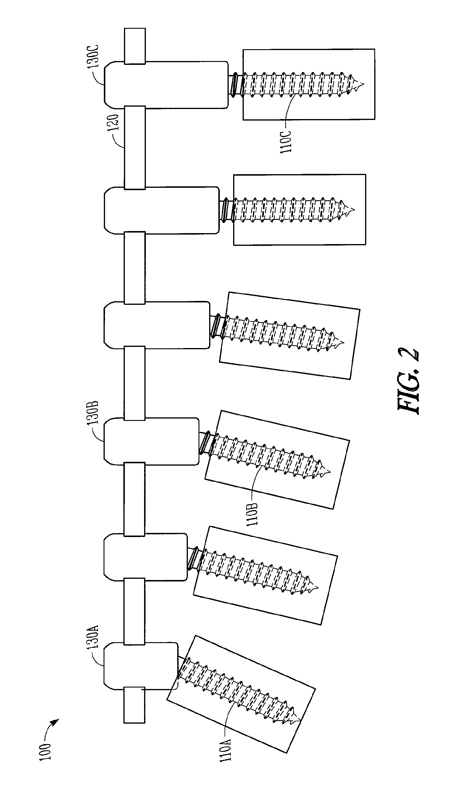
[0015]Referring to FIGS. 1 and 2, a spine fixation system 100 is provided that includes a plurality of bone anchors 110A, 110B, 110C, a plurality of anchor seats 130A, 130B, 130C, a plurality of collets 152, and a plurality of locking caps 140A, 140B, 140C. The syst...


PUM


Abstract

A minimally invasive system and method for coupling a spinal rod to a plurality of bone anchors implanted into a plurality of vertebral bodies. A plurality of bottom-loading polyaxial anchor seat assemblies having different vertical heights are chosen to pop over the heads of the implanted bone anchors and a spinal rod is more easily introduced and secured to the bone anchors. The variety of different heights that characterize the plurality of polyaxial anchor seat assemblies allows a surgeon to intraoperatively choose the appropriate offset for a particular spinal level during spinal corrections.

Description

BACKGROUND OF THE INVENTION[0001]Minimization of surgical steps during posterior screw and rod placement during some spinal surgeries is desirable. Current top loading polyaxial pedicle screw systems, in which the bone anchor is loaded manually into the down through the top of the anchor seat just prior to the surgery or, more often, in which the combination comes preassembled, typically requires several surgical steps after an incision and access path are provided. These steps may include implantation of multiple polyaxial screw and anchor seat assemblies, insertion of a spinal rod into the multiple screw and anchor seat assemblies insertion of a locking cap into each screw and anchor seat assembly and tightening of the locking cap onto each screw and anchor seat assembly for locking the construct. Seating of the rod and insertion of the multiple locking caps can be challenging due to the anatomical placement of the bone anchors, the nature of the anatomical correction required, le...

Claims


Application Information

Patent Timeline
IPC IPC(8): A61B17/70A61B17/88A61B17/86
CPCA61B17/7037A61B17/7032A61B17/70A61B17/86
Inventor JACOB, R. PATRICKMCDIVITT, ERICCAPOZZOLI, JOSEPHKEYER, THOMAS
Owner DEPUY SYNTHES PROD INC
Learn More