DETAILED DESCRIPTION OF THE DRAWINGS
[0029]In the following description of the drawings the same numerals designate the same or comparable components.
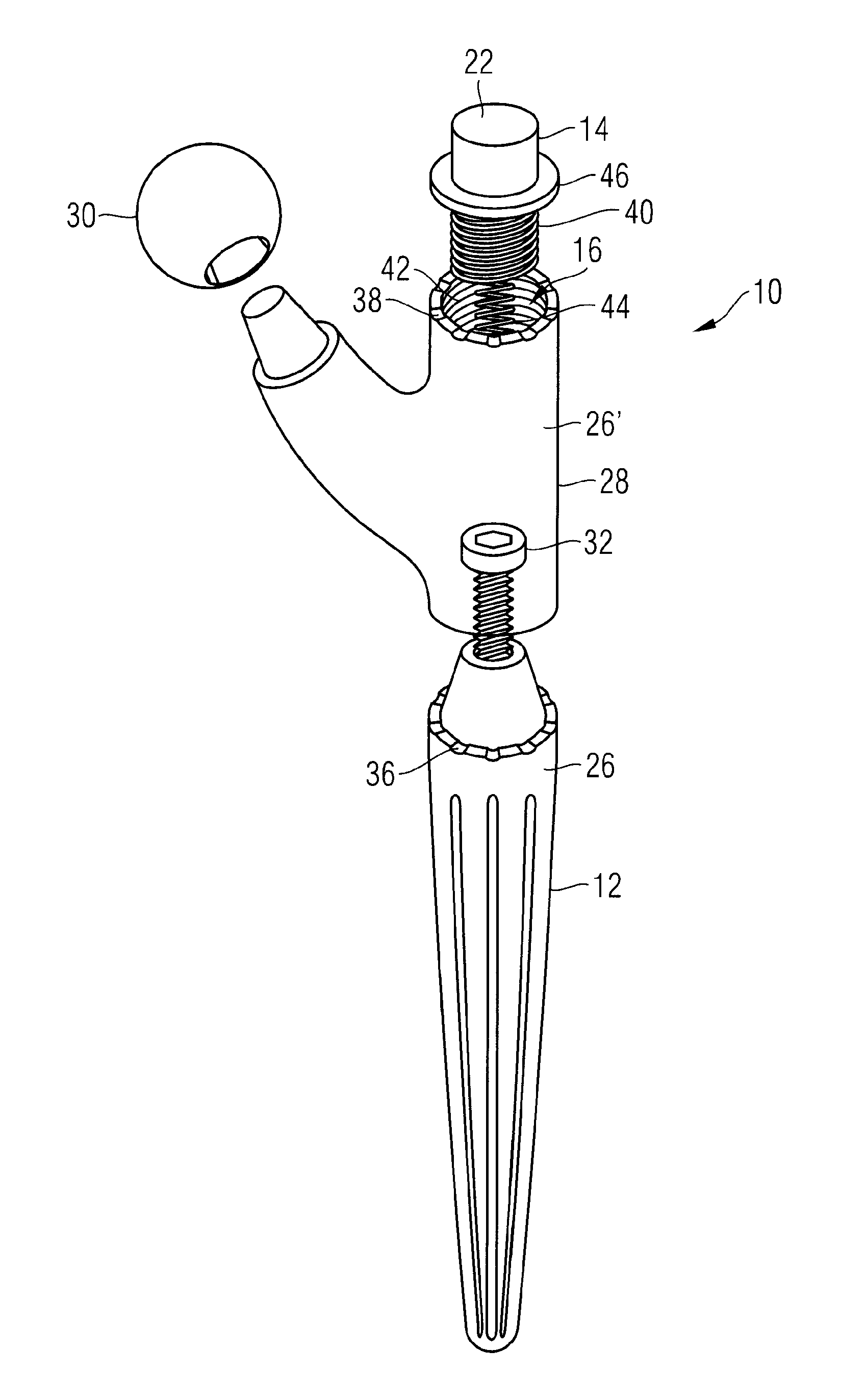
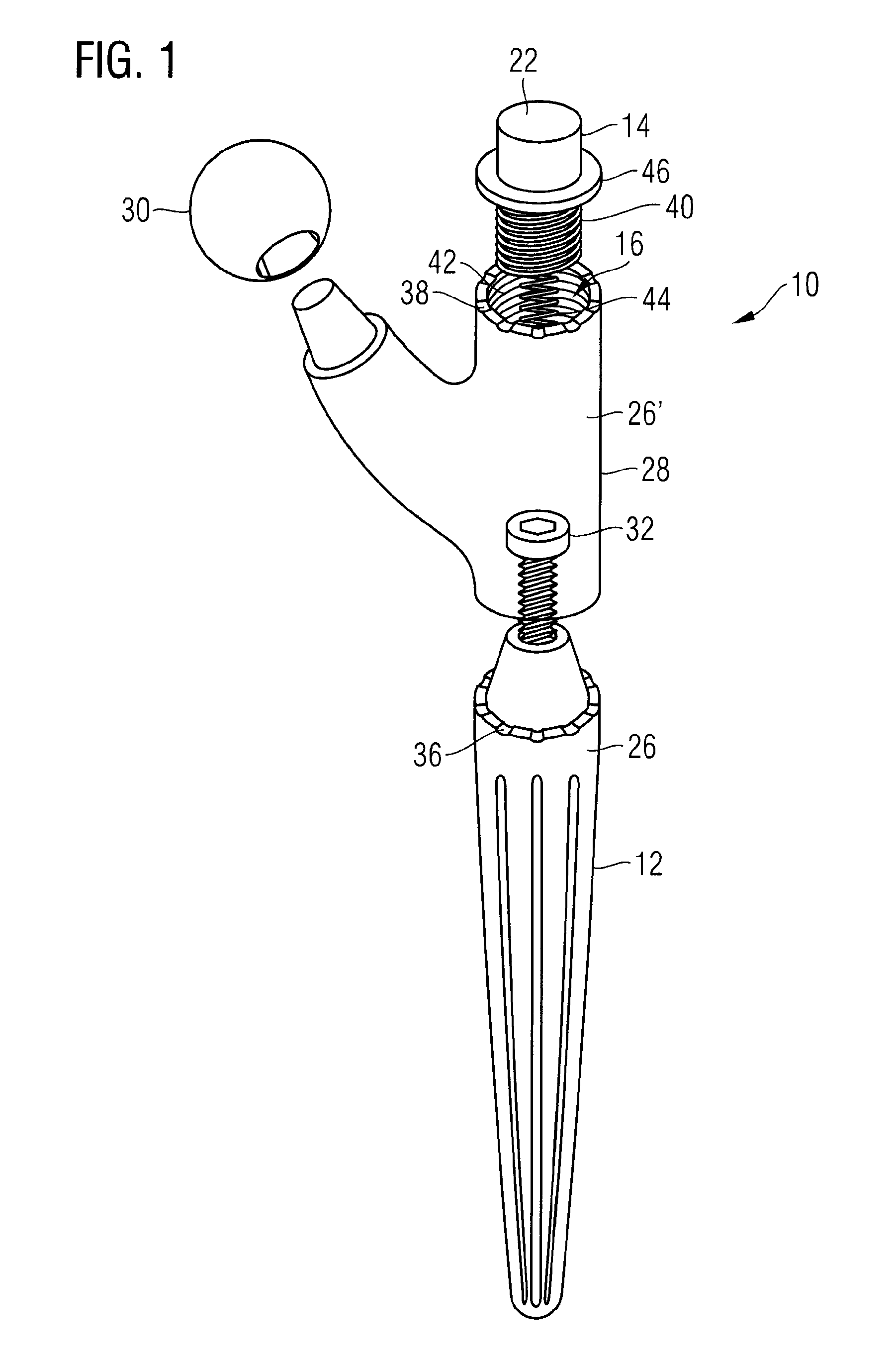
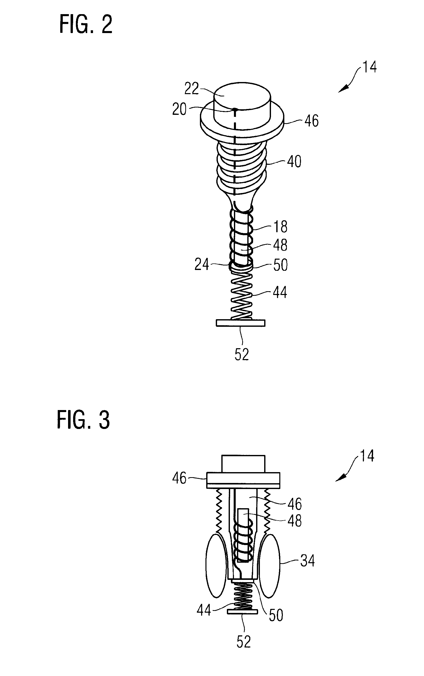
[0030]FIG. 1 shows a perspective exploded view of a hip joint prosthesis 10 according to the invention. The hip joint prosthesis 10 comprises a shaft-like section 12, a neck section 28, a femoral head 30, and an end cap assembly 14. The neck section 28 is connectable to the shaft-like section 12 by means of a screw 32. The end cap assembly 14 comprises a male thread 40 which is screwable into a female thread 42 of the neck section 28. Inside the end cap assembly 14, electric components are arranged which will be described in more detail in connection with FIGS. 2 and 3. One pole of these electric components is electrically connected to a spring 44 carried by the end cap assembly 14. In the assembled state of the hip joint prosthesis 10, i.e., with the neck section 28 connected to the shaft-like section 12 by means of the screw 32 and the screwed-on end cap assembly 14 closing the hollow space 16, said spring 44 electrically contacts the axially arranged screw 32 directly or indirectly so that the shaft-like section 12 and/or the neck section 28 receive the electric potential of the spring 44. Therefore, the conductive surface sections of the shaft-like section 12 and/or the neck section will become electrodes 26, 26′. Another pole of the electric assembly is, for example, connected to a surface of the end cap assembly 14 so that the end cap 14 forms the counter electrode 22 to the electrode 26, 26′ described above.
[0031]FIG. 2 shows a perspective exploded view of an end cap assembly 14 of a hip joint prosthesis 10 according to the invention, and FIG. 3 shows an axial cross section of an end cap assembly 14 of a hip joint prosthesis 10 according to the invention. The end cap assembly 14 comprises a hollow space 46. A coil assembly 18 wound on an iron core 48 is insertable into the hollow space 46. After the insertion of the assembly into the hollow space 46, the assembly may be cemented into it, for example, using an epoxy resin adhesive, and the hollow space 46 may be distally closed by a panel 50, preferably by cementing the panel 50 to the threaded portion tapered in the distal direction. The metallic panel 50 electrically contacts a pole 24 of the coil assembly 18. The other pole 20 of the coil assembly 18 is connected to an electrically conductive surface 22 of the end cap assembly 14. The panel 50 is followed by the electrically conductive spring 44 already mentioned in connection with FIG. 1 in the distal direction, to which in turn an electrically conductive panel 52 is distally attached. If the end cap assembly 14 is inserted into the hip joint prosthesis, the panel 52 will establish an electric contact to the screw 32 (see FIG. 1). On this basis, different configurations of surface electrodes can be realised. For example, the body of the end cap assembly 14 carrying the thread 40 can formed so as to be electrically insulating, preferably from aluminum oxide or zirconium oxide ceramics (Al2O3 or ZrO2). A part of the surface the end cap assembly will then be transferred into an electrically conductive state, for example by sputtering or vaporizing an electrically conductive material. With the metallic panel 52 being connected to the screw 32 and, in turn, the screw 32 contacting the neck section 28 as well as the shaft-like section 12—both of which are manufactured from an electrically conductive metal—the neck section 28 and the shaft-like section 12 together form the counter electrode to the electrically conductive surface of the end cap assembly 14. It is also feasible to configure the screw 32 so as to be insulating and to ensure that no electric contact exists between the neck section 28 and the shaft-like section 12. Then, by establishing an electric contact, only the neck section 28 or parts of the neck section 28 may form the counter electrode to the end cap assembly 14. An electric contact between the distal pole of the coil assembly and the neck section 28 can also be avoided while an electric contact is established between this pole 24 and the shaft-like section. The electrically conductive surface of the end cap assembly 14 and the shaft-like section 12 then form counter electrodes without the involvement of the neck section 28. With a further embodiment, it is also possible that the end cap assembly 14 does not serve as an electrode. This may be realised in that the end cap assembly 14 is completely insulating on its surface, and the first pole 20 of the coil assembly 18 contacts the neck section 28 when the end cap assembly 14 is screwed into the neck section 28, for example, by a squeeze contact by means of the collar 46 of the end cap assembly.
[0032]FIG. 3 shows a useful embodiment of an end cap assembly 14 provided with another functionality. The end cap assembly 14 carries a drug reservoir 34. This drug reservoir is provided for local antibiosis in particular. The outer surface of the drug reservoir 34 is configured as a pressure-permeable wall so that a liquid drug solution can leak out when the end cap assembly 14 is screwed into the hollow space 16 (see FIG. 1) as the drug reservoir 34 is then compressed. Liquid leaking from the drug reservoir 34 may then leak from the hollow space 16 into the space outside of the hip joint prosthesis 10 through the openings 36, 38. Since it may also be useful not to have the drug solution leak into the neck section 28 as early as during the process of screwing in the end cap assembly 14, it may be contemplated that a drug pump which is directly or indirectly supplied with electric power by the coil assembly 18 is provided in the hollow space 16 of the neck section 28. For example, the coil assembly 18 may charge an accumulator which then provides the electric power required for the operation of the drug pump at any time. The operation of the drug pump may be controlled by a conventional transmitter-receiver device. It is also feasible to release the mechanic energy required for the timed discharge by a component responsive to a magnetic impulse.
[0033]The features of the invention disclosed in the above description, the drawings as well as the claims may be important for the realization of the invention individually as well as in any combination.
LIST OF REFERENCE NUMERALS
[0034] 10 hip joint prosthesis [0035] 12 shaft-like section [0036] 14 end cap assembly [0037] 16 hollow space [0038] 18 coil assembly [0039] 20 first pole [0040] 22 first electrode [0041] 24 second pole [0042] 26 second electrode [0043] 28 neck section [0044] 30 femoral head [0045] 32 fixation means; electrically insulating screw [0046] 34 drug reservoir; pressure permeable container [0047] 36 opening [0048] 38 opening [0049] 40 male thread [0050] 42 female thread [0051] 44 electrically conductive spring [0052] 46 hollow space [0053] 48 iron core [0054] 50 panel [0055] 52 panel