
Vehicle seat

a technology for vehicles and seats, applied in the field of vehicles seats, can solve the problems of undesirable narrowness and undesirable deterioration of the luggage compartment of the vehicle, and achieve the effect of reducing the size of the luggage compartment and reducing the size of the vehicl

Inactive Publication Date: 2012-02-23
TOYOTA SHATAI KK +1
View PDF7 Cites 4 Cited by
  • Summary
  • Abstract
  • Description
  • Claims
  • Application Information

AI Technical Summary

Benefits of technology

[0011]Accordingly, it is an objective of the present invention to provide a vehicle seat that has a reduced projecting amount of a leg from a cushion frame into the space in the passenger compartment, thus reducing the thickness of a seat cushion, increasing the width of the luggage compartment of the vehicle, accordingly, and reducing deterioration of the appearance.
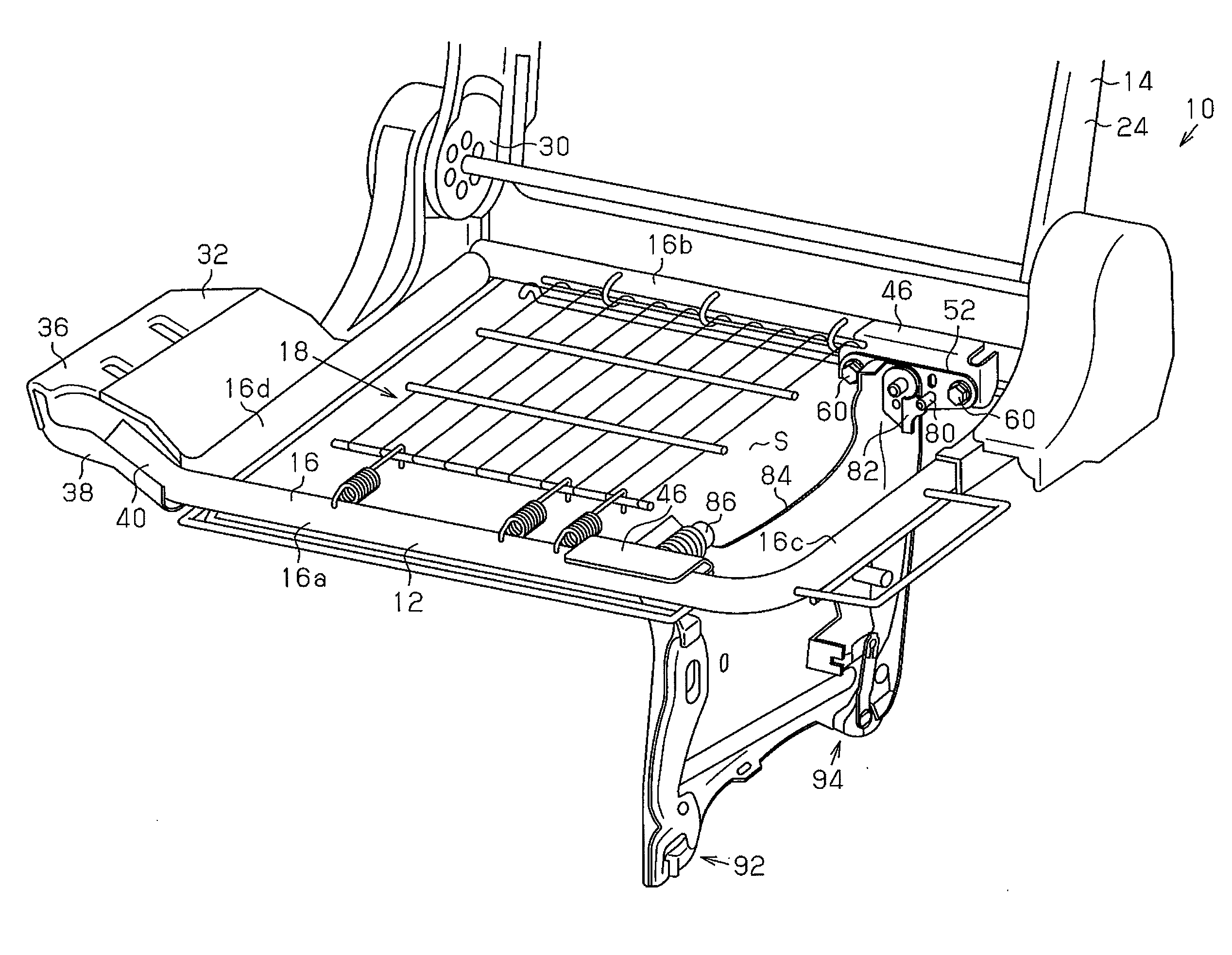
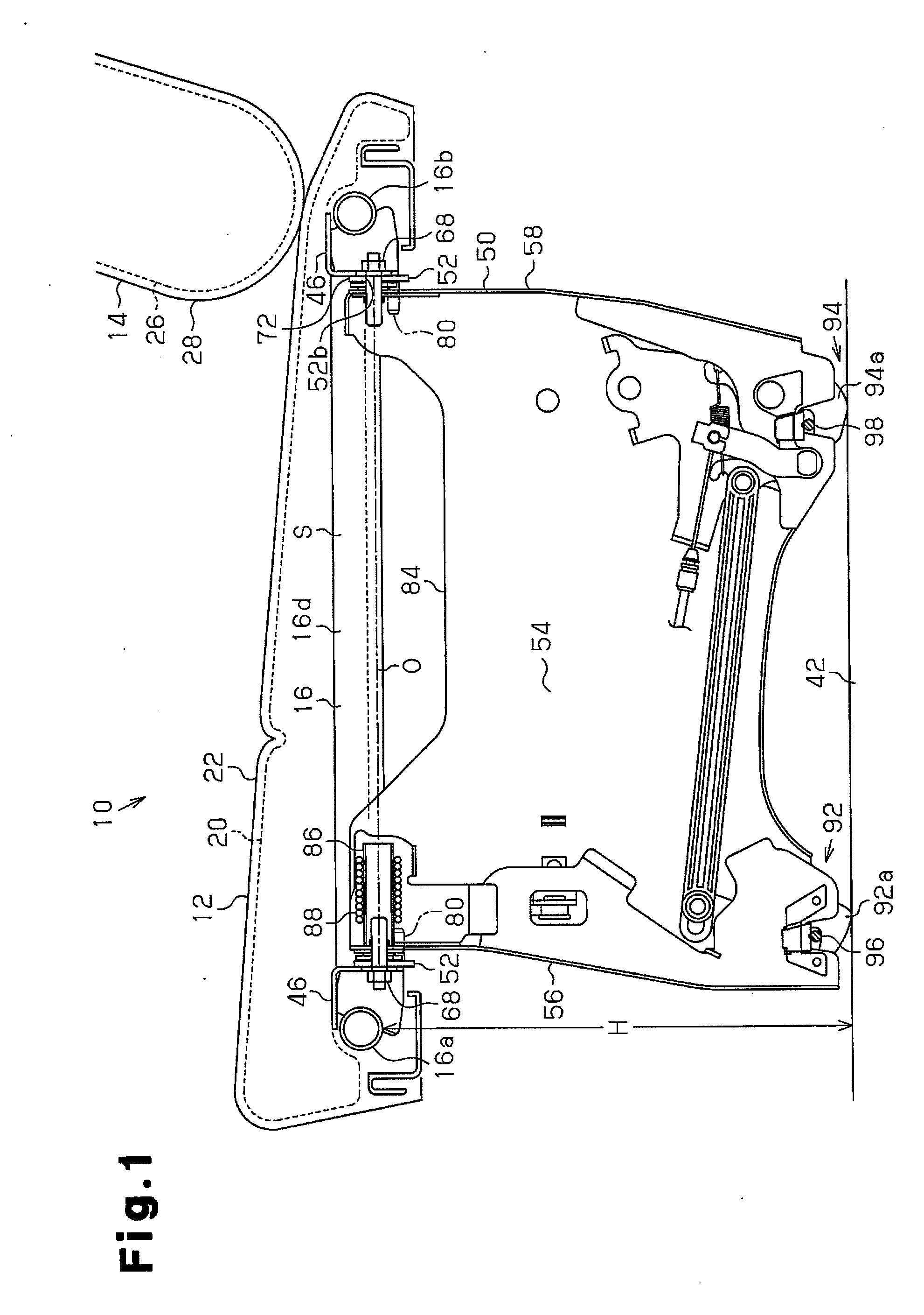
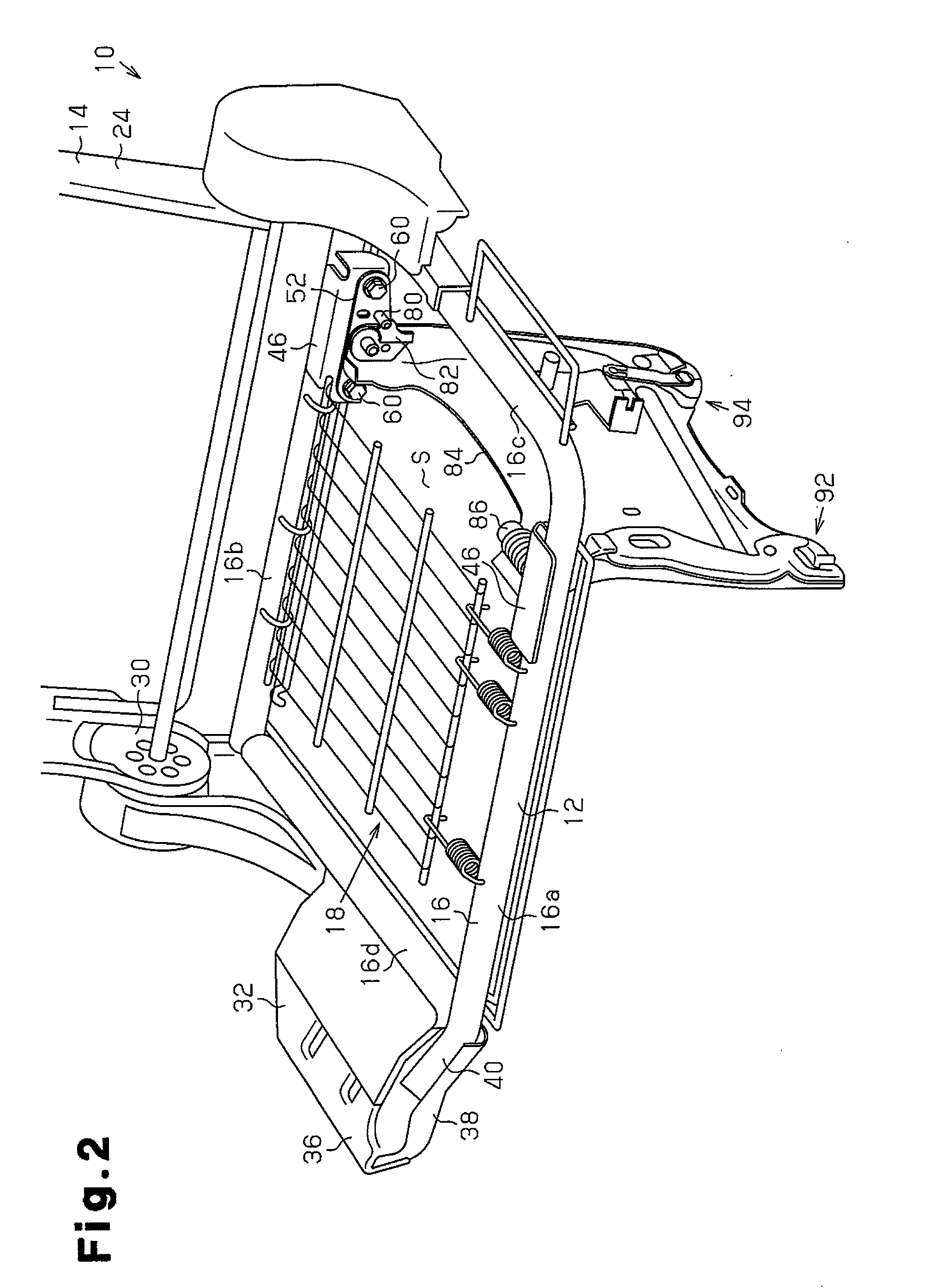
[0013]With this structure, when the seat cushion is flipped up to the position along the side wall of the passenger compartment, at least part of the leg is accommodated in the space surrounded by the cushion frame. Thus, the folded leg is prevented from projecting from the cushion frame by an amount corresponding to the thickness of the accommodated portion. As a result, the projecting amount of the leg into the space in the passenger compartment from the cushion frame is reduced, thereby reducing the thickness of the part below the seat cushion, and increasing the width of the luggage compartment of the vehicle by the amount corresponding to the reduced thickness. This reduces deterioration of the appearance.
[0015]With this structure, the bracket pivotably supporting the leg is arranged to be located in the space surrounded by the cushion frame. Thus, the leg is easily accommodated in the cushion frame.

Problems solved by technology

Therefore, in a state in which the seat cushion is flipped up, the width of the luggage compartment of the vehicle undesirably becomes narrow.
Also, if the projecting amount of the leg from the cushion frame is great, the appearance is undesirably deteriorated.Patent Document 1: Japanese Laid-Open Patent Publication No. 8-142725Patent Document 2: Japanese Laid-Open Patent Publication No. 10-109578Patent Document 3: Japanese Laid-Open Patent Publication No. 11-147432Patent Document 4: Japanese Laid-Open Patent Publication No. 2008-126742

Method used


Image

  • Vehicle seat
  • Vehicle seat
  • Vehicle seat

Examples


Embodiment Construction

[0029]A vehicle seat according to one embodiment of the present invention will now be described with reference to FIGS. 1 to 7.

[0030]The vehicle seat 10 is arranged in a passenger compartment, and includes a seat cushion 12 and a seat back 14 pivotably coupled to the rear portion of the seat cushion 12 as shown in FIGS. 1 and 2. The seat cushion 12 includes a cushion frame 16, a pad 20 supported by a spring body 18 mounted on the cushion frame 16 in a tensioned state, and a surface material 22 for covering the pad 20. The cushion frame 16 is formed of a pipe material having a circular cross section, and includes a front frame 16a and a rear frame 16b arranged on the front and rear sides of the seat 10, and a left frame 16c and a right frame 16d arranged on the left and right sides of the seat 10. The cushion frame 16 is not limited to be formed of pipe material having a circular cross-section, but may be formed of a pipe material having a rectangular cross-section, and may be formed...


PUM


Abstract

A leg (50) is pivotably supported by a cushion frame (16) such that part of the leg (50) is accommodated in a space (S) surrounded by the cushion frame (16). When the leg (50) is folded, part of the leg (50) is accommodated in the space (S) surrounded by the cushion frame (16). Thus, when the seat cushion (12) is flipped up to a storage position along a side wall (34) of the passenger compartment, part of the leg (50) is accommodated in the space (S) surrounded by the cushion frame (16). This prevents the leg (50) from projecting from the cushion frame (16) by the amount corresponding to the thickness of the accommodated portion.

Description

TECHNICAL FIELD[0001]The present invention relates to a vehicle seat that can be flipped up toward a side wall of a passenger compartment.BACKGROUND ART[0002]Conventionally, single-box vehicles such as station wagons and vans include a third vehicle seat row in addition to the front and rear seat rows. A seat in such a third seat row is disclosed in, for example, Patent Documents 1 to 4. The legs for a seat cushion of the vehicle seat are detachably located on the vehicle floor.[0003]When in use, the seat cushion is arranged at a horizontal use position, and a seat back is arranged upright on the seat cushion. When the vehicle seat is stored, the seat back is collapsed onto the seat cushion, and in a state in which the leg is detached from the vehicle floor, the seat cushion and the seat back are flipped up along the side wall of the vehicle floor to be arranged in a storage position.[0004]In such a flip-up vehicle seat, mounting lugs extend from a cushion frame of the seat cushion,...

Claims


Application Information

Patent Timeline
Patent Type & Authority Applications(United States)
IPC IPC(8): B60N2/30B60N2/02
CPCB60N2/01583B60N2/7094B60N2/3043B60N2/3011
Inventor KURACHI, SHINJIHATTORI, RYOUMAETA, TOSHIHIKOKONAGAI, AKIRA
Owner TOYOTA SHATAI KK
Learn More