

Roof ventilation system
- Summary
- Abstract
- Description
- Claims
- Application Information
AI Technical Summary
Benefits of technology
Problems solved by technology
Method used
Image

Examples
Embodiment Construction
[0019]The present invention relates to the general field of roof ventilation systems. More specifically an improved air permeable roof closure ventilation. The following description is presented to enable one of ordinary skill in the art to make and use the invention and to incorporate it in the context of particular applications. Various modifications, as well as a variety of uses in different applications will be readily apparent to those skilled in the art, and the general principles defined herein may be applied to a wide range of embodiments. Thus, the present invention is not intended to be limited to the embodiments presented, but is to be accorded the widest scope consistent with the principles and novel features disclosed herein.
[0020]Overview:
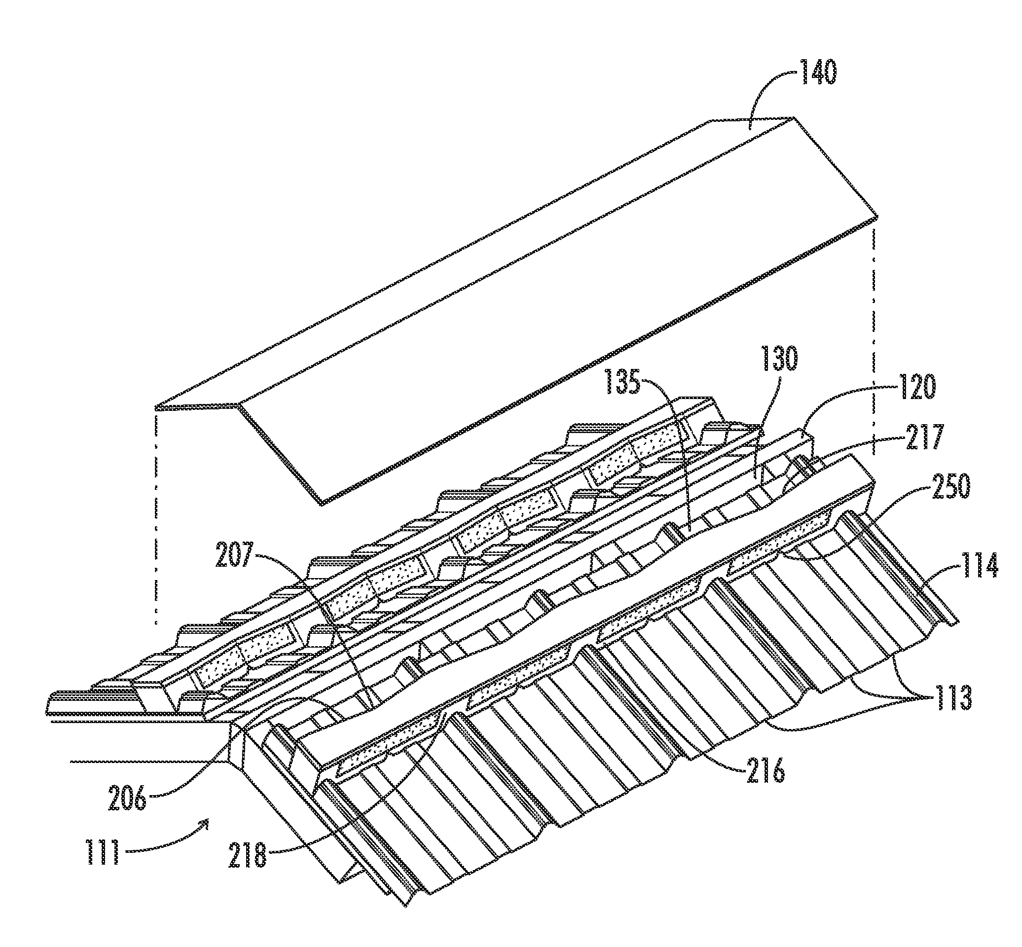
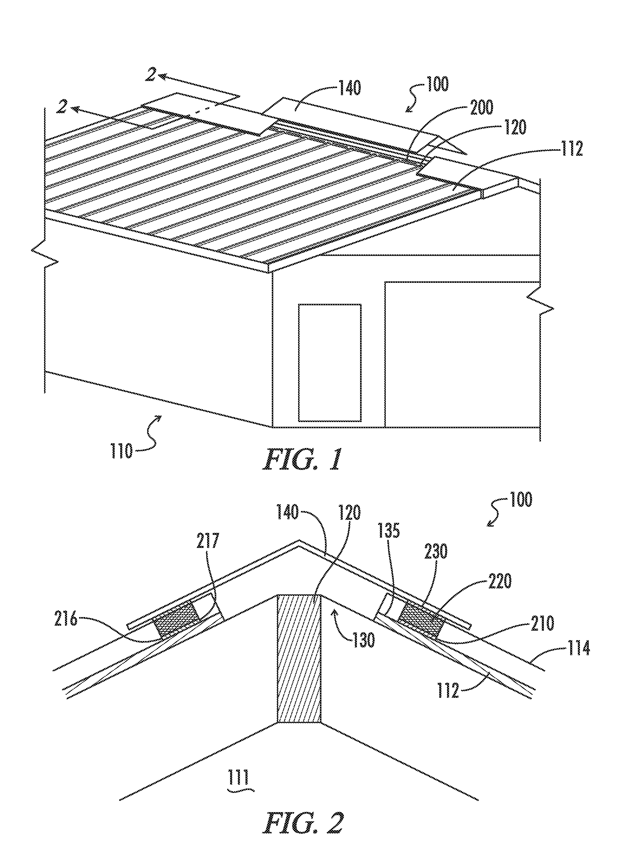
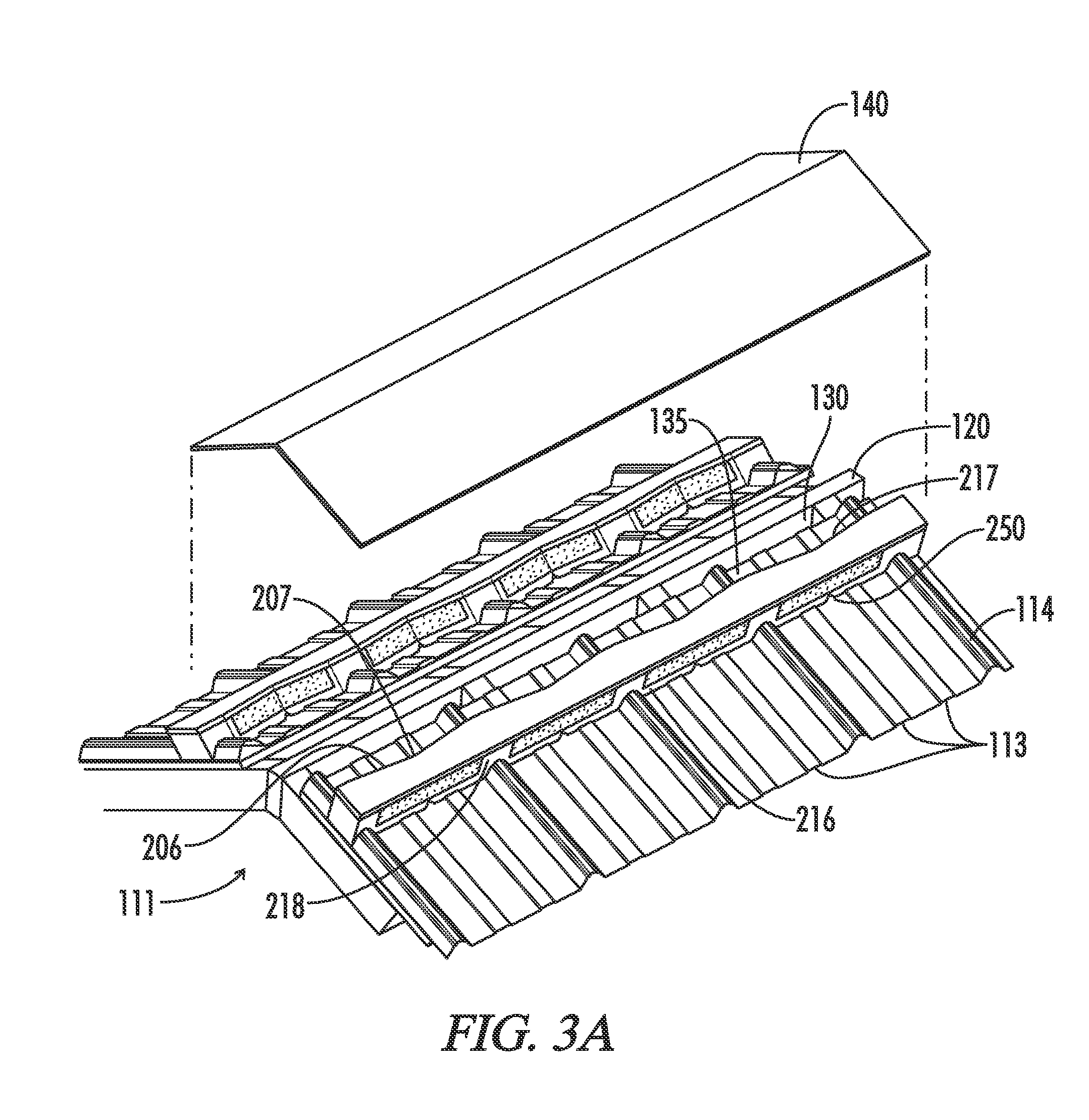
[0021]As illustrated in FIGS. 1 through 10, a roof closure ventilation system 100 comprises a structure 110 that includes a sloped roof 112 having multiple roofing sections joined at one or more sides with elongated ribs or overlappin...
PUM
 Abstract
Description
Claims
Application Information