
Head-mounted display with eye state detection

a display and eye state technology, applied in the field of head-mounted displays, can solve the problems of low image quality of combined images produced by this method, low image quality that is difficult to interpret, and unsuitable for viewing high-quality images, etc., to achieve the effect of improving viewing comfort, reducing motion sickness, and high quality

Inactive Publication Date: 2012-03-01
EASTMAN KODAK CO
View PDF10 Cites 44 Cited by
  • Summary
  • Abstract
  • Description
  • Claims
  • Application Information

AI Technical Summary

Benefits of technology

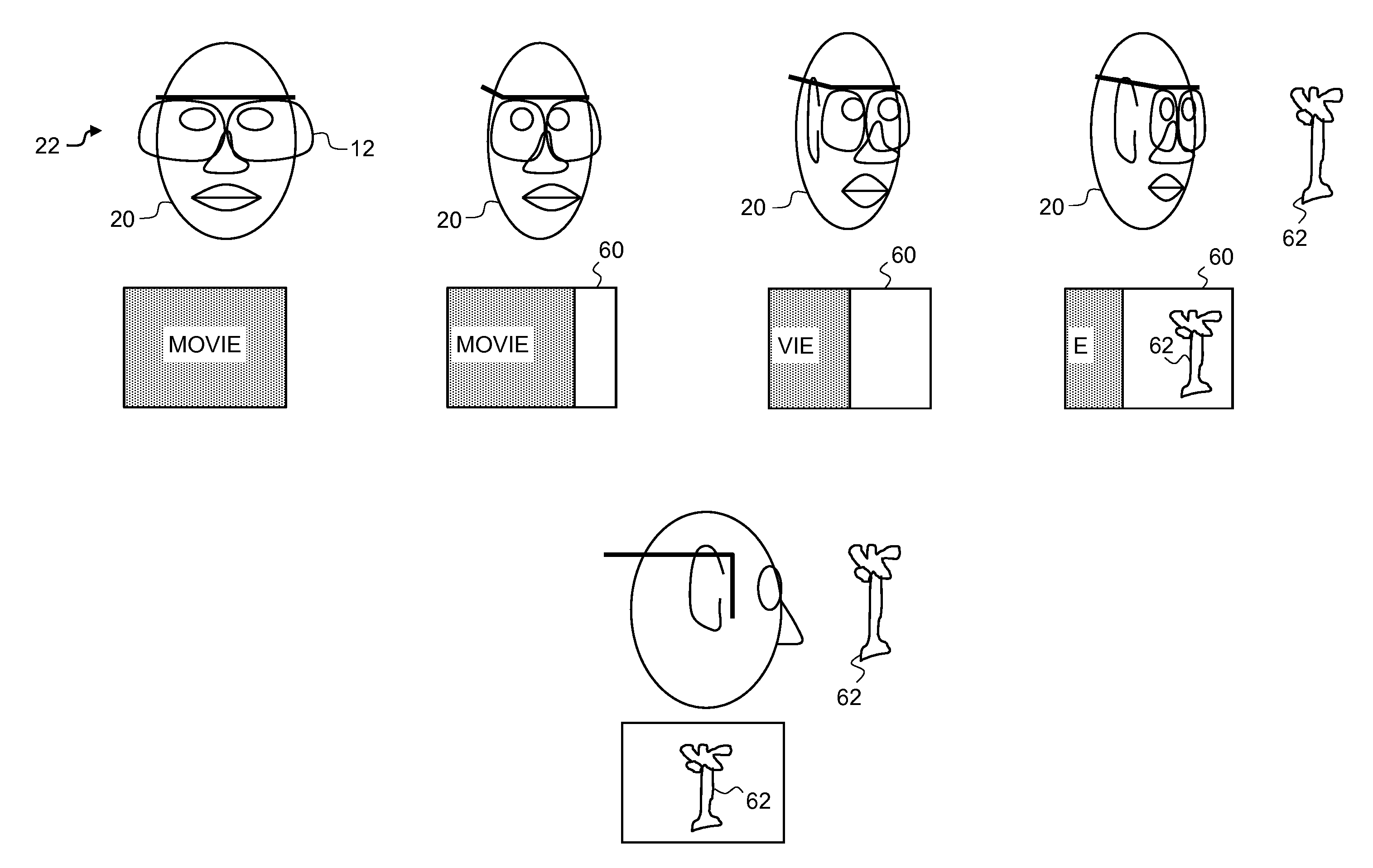
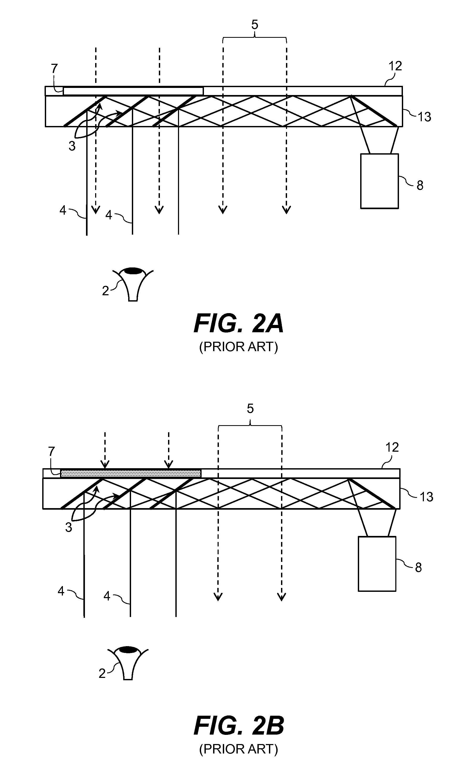
[0021]i) the transparent state enables a user of the head-mounted display to see the real world outside the head-mounted display in the user's line of sight;
[0025]The present invention provides an improved head-mounted display that enables viewing of high quality image information with reduced motion sickness and improved viewing comfort for the user in response to an external stimulus.

Problems solved by technology

Combined images produced with this method are of a low image quality that is difficult to interpret as shown in FIG. 4.
Motion sickness or simulator sickness is a known problem for immersive displays because the user cannot see the environment well.
Motion sickness is less of an issue for augmented reality displays since the user can see the environment better, however, the imaging experience is not suitable for viewing high quality images such as movies with a see-through display due to competing image information from the external scene and a resulting degradation in contrast and general image quality.
In this paper, the specific problem of image movement lagging behind the head movement of the user is investigated as a cause of motion sickness.

Method used


Image

  • Head-mounted display with eye state detection
  • Head-mounted display with eye state detection
  • Head-mounted display with eye state detection

Examples


Embodiment Construction

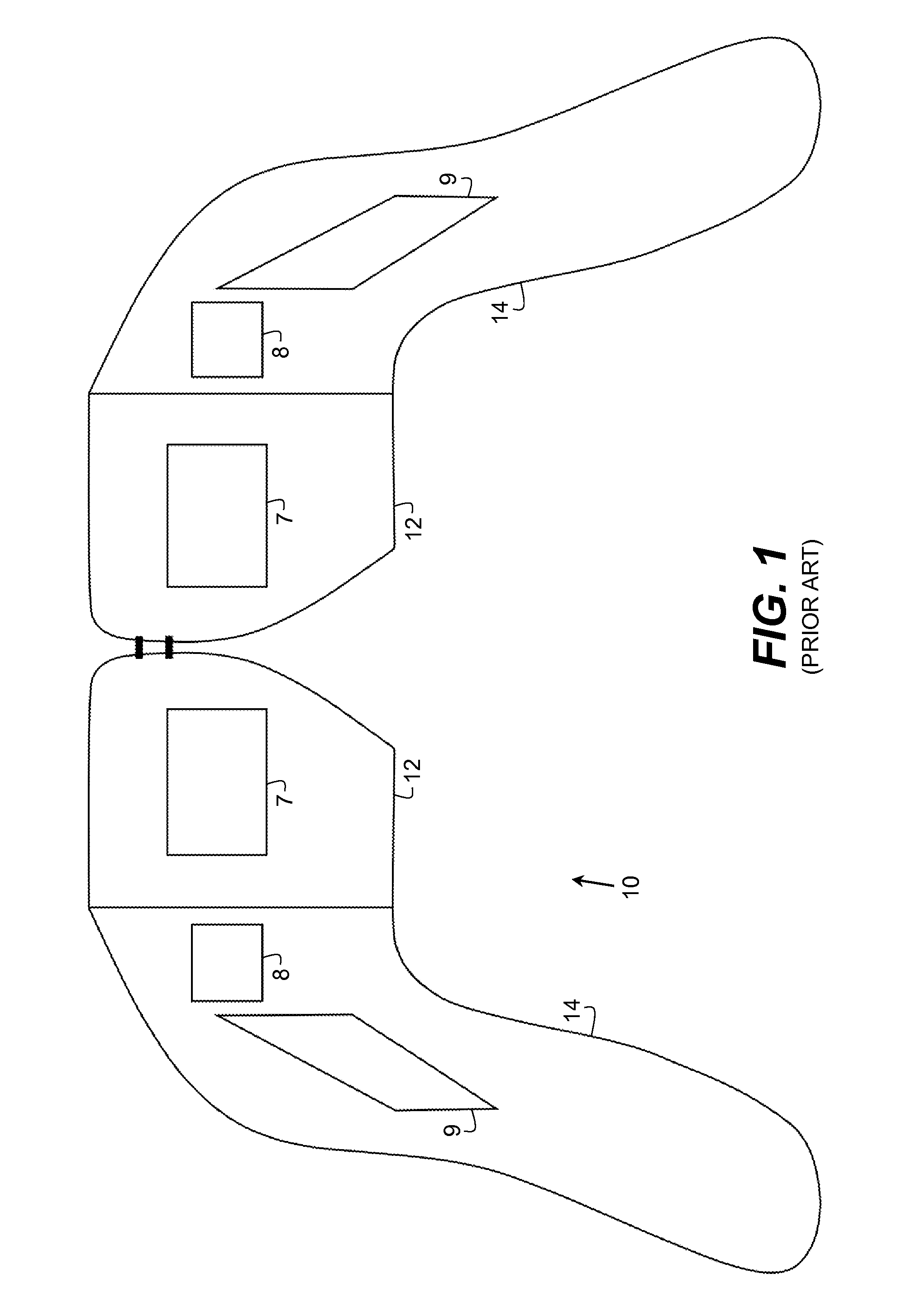
[0044]A wide variety of head-mounted displays are known in the art. The head-mounted displays include a microprojector or image scanner to provide image information, relay optics to focus and transport the light of the image information to the display device and a display device that is viewable by the user's eyes. Head-mounted displays can provide image information to one eye of the user or both eyes of the user. Head-mounted displays that present image information to both eyes of the user can have one or two microprojectors. Monoscopic viewing in which the same image information is presented to both eyes is done with head-mounted displays that have one or two microprojectors. Stereoscopic viewing typically requires a head-mounted display that has two microprojectors.

[0045]The microprojectors include image sources to provide the image information to the head-mounted display. A variety of image sources are known in the art including, for example, organic light-emitting diode (OLED) ...


PUM


Abstract

Control of a head-mounted display includes providing a head-mounted display, the head-mounted display includes a switchable viewing area that is switched between a transparent viewing state and an information viewing state. The transparent viewing state is transparent with respect to the viewing area and enables a user of the head-mounted display to view the scene outside the head-mounted display in the user's line of sight. The information viewing state is opaque with respect to the viewing area and displays information in the switchable viewing area visible to a user of the head-mounted display. A user-eye detector provides an external stimulus notification in response to a detected change in the state of the eye of the user; and causes the viewing state to automatically switch in response to the external stimulus notification.

Description

CROSS REFERENCE TO RELATED APPLICATIONS[0001]Reference is made to commonly assigned U.S. patent application Ser. No. ______ filed concurrently herewith, entitled “Head-Mounted Display Control by John N. Border et al; U.S. patent application Ser. No. ______ filed concurrently herewith, entitled “Head-Mounted Display With Biological State Detection” by John N. Border et al; U.S. patent application Ser. No. ______ filed concurrently herewith, entitled “Head-Mounted Display With Environmental State Detection” by John N. Border et al, and U.S. patent application Ser. No. ______ filed concurrently herewith, entitled “Switchable Head-Mounted Display” by John N. Border et al, the disclosures of which are incorporated herein.FIELD OF THE INVENTION[0002]The present invention relates to a head-mounted display. More particularly, the present invention relates to a control method for reducing motion sickness when using such a display in response to an external stimulus.BACKGROUND OF THE INVENTIO...

Claims


Application Information

Patent Timeline
IPC IPC(8): G09G5/00
CPCG09G3/3611G09G2340/04G09G2354/00G02B2027/0187G02B2027/0178G02B2027/0118G02B27/0101
Inventor BORDER, JOHN N.COK, RONALD S.FEDOROVSKAYA, ELENA A.WANG, SENLANDRY, LAWRENCE B.KANE, PAUL J.
Owner EASTMAN KODAK CO
Learn More