Wavelength conversion structure and light source apparatus
a technology of wavelength conversion structure and light source, which is applied in the direction of lighting and heating apparatus, semiconductor lasers, instruments, etc., can solve the problems of human eye damage, retina damage, and laser light damage,
- Summary
- Abstract
- Description
- Claims
- Application Information
AI Technical Summary
Benefits of technology
Problems solved by technology
Method used
Image

Examples
first embodiment
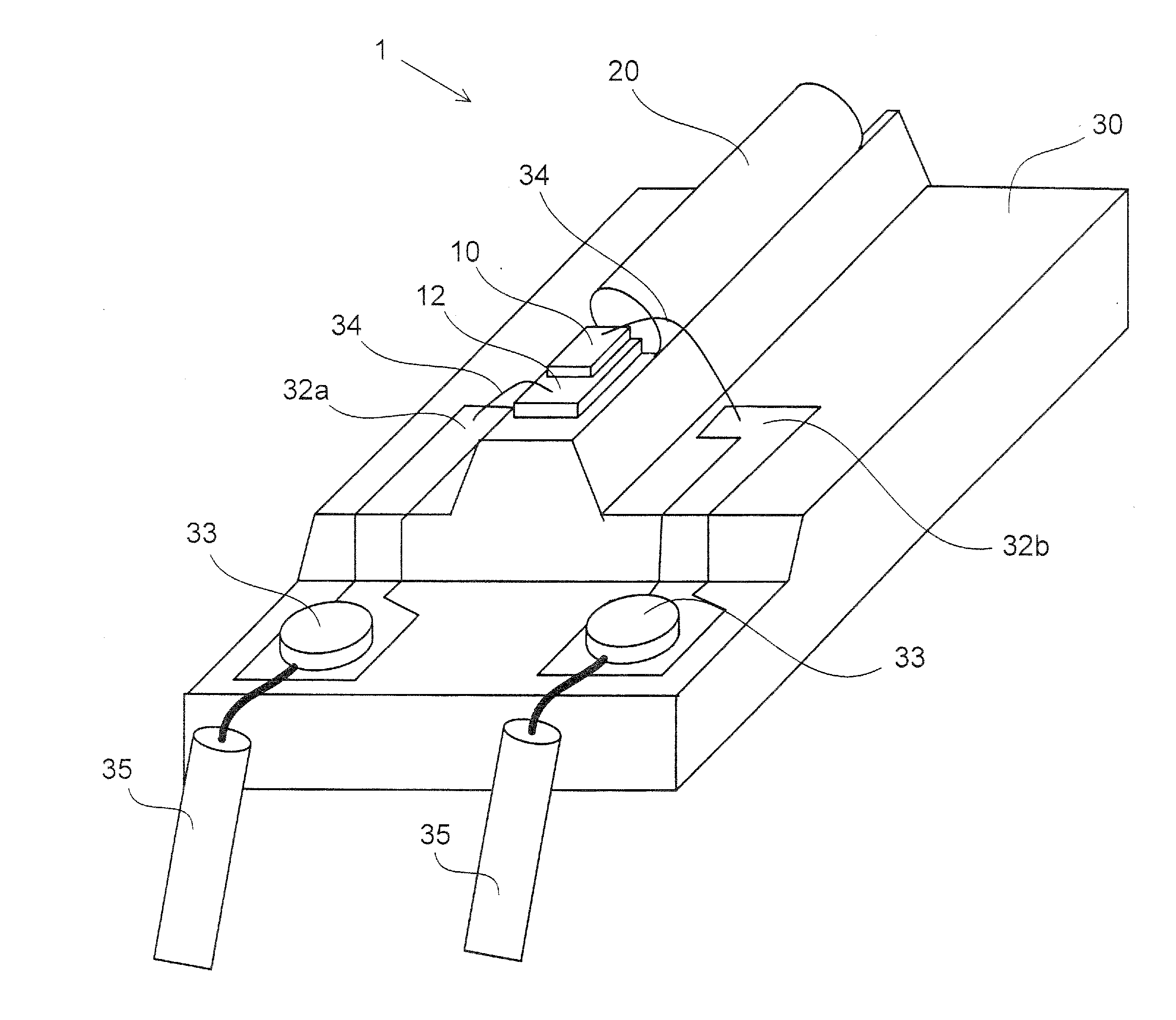
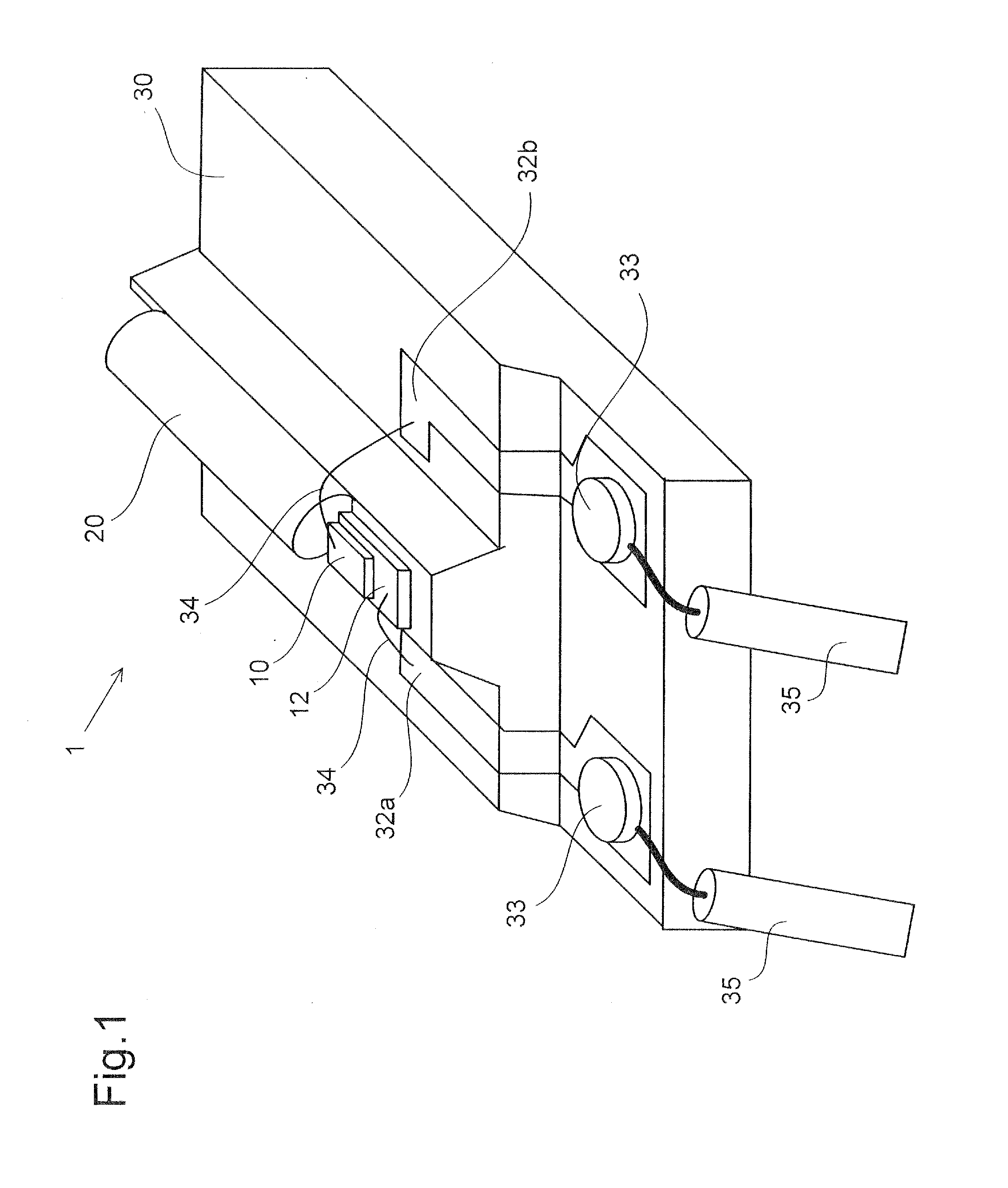
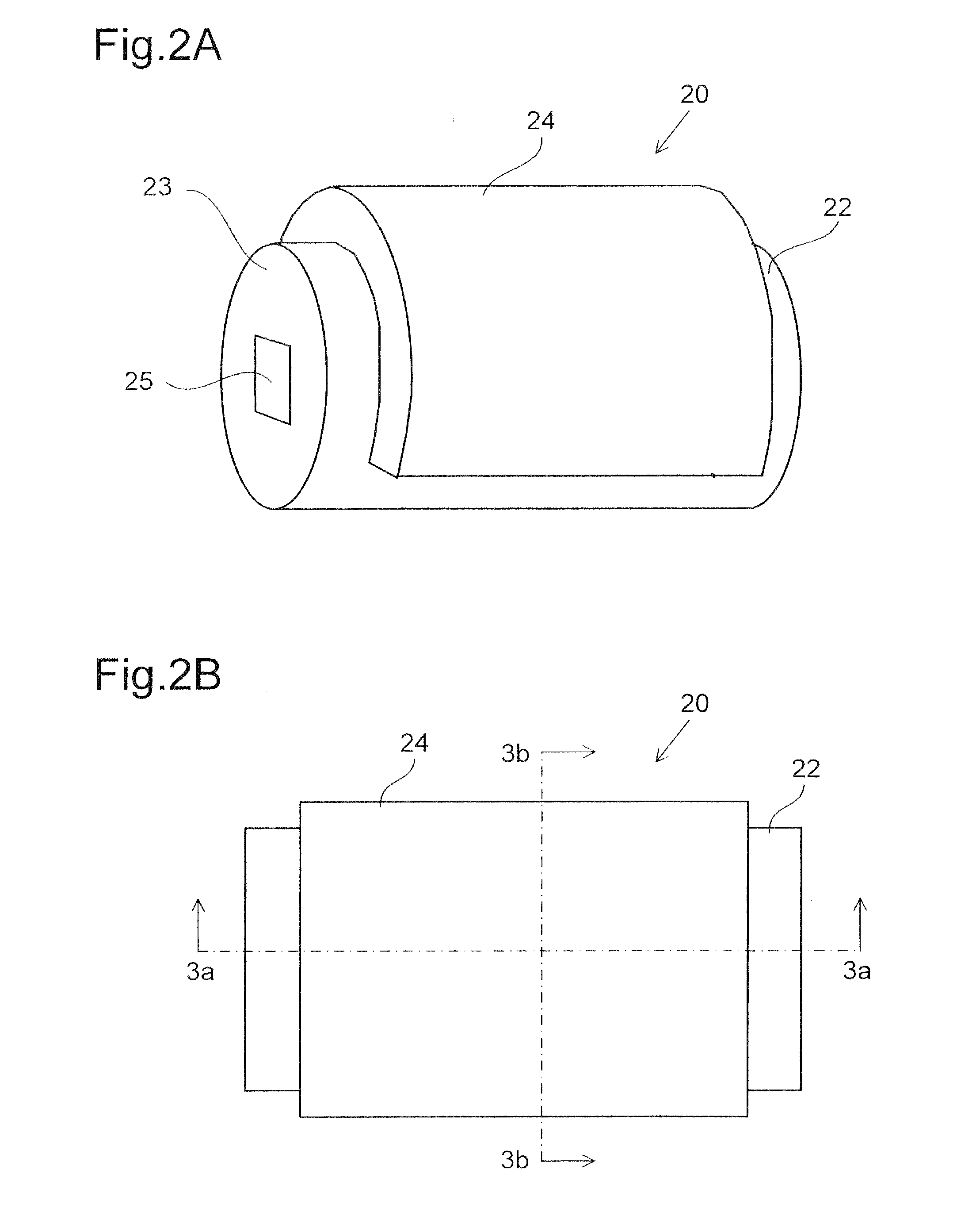
[0027]A light source apparatus according to a first embodiment of the invention will be described below. FIG. 1 is a perspective view showing the configuration of a light source apparatus 1 according to the first embodiment of the invention. FIGS. 2A and 2B are a perspective view and a plan view showing the configuration of a wavelength conversion structure 20 that forms part of the light source apparatus 1, respectively. FIGS. 3A and 3B are cross-sectional views taken along the lines 3a-3a and 3b-3b in FIG. 2B, respectively.
[0028]A laser diode 10 is an edge-emitting semiconductor laser including a semiconductor layer made of GaN or any other suitable nitride-based semiconductor and emitting blue light having a wavelength of about 450 nm through an end surface or facet of a semiconductor chip. The laser diode 10 has a top-surface electrode provided over a principal surface thereof, and no laser light is emitted through the principal surface. The laser diode 10 is mounted on a sub-mo...
second embodiment
[0055]FIG. 7A is a cross-sectional view showing the configuration of a wavelength conversion structure 20a according to a second embodiment of the invention. The wavelength conversion structure 20a differs from the wavelength conversion structure 20 according to the first embodiment described above in that a polarization filter 40 for blocking return light directed to the laser diode 10 is provided adjacent to the laser-light incident end surface 23 of the light guide 22.
[0056]The polarization filter 40 transmits only light having an amplitude component polarized in a specific direction. The polarization filter 40 is designed to transmit linearly polarized laser light emitted from the laser diode 10 and directed toward the light guide 22. The laser light introduced into the light guide 22 is diffused and scattered by the light diffusing structure formed over the surface of the light guide 22 so that the oscillating direction of the laser light is changed. Since the laser light havin...
third embodiment
[0058]FIG. 8A is a perspective view showing the configuration of a wavelength conversion structure 20c according to a third embodiment of the invention, and FIG. 8B is a cross-sectional view showing the configuration of a light source apparatus 2 according to the third embodiment of the invention including the wavelength conversion structure 20c. The wavelength conversion structure 20c includes the cylindrical light guide 22 and a phosphor-containing resin 24c that covers the entire circumferential side surface of the light guide 22. That is, the phosphor-containing resin 24c has a cylindrical shape and accommodates the light guide 22 therein. In other words, the phosphor-containing resin 24c is formed within a range corresponding to a central angle of 360° along the side surface of the light guide 22. The light guide 22 has microscopic asperities over the surface thereof except the laser-light incident end surface 23, and the light reflecting film 26 is formed on the surface of the...
PUM
 Abstract
Description
Claims
Application Information
 - Generate Ideas
- Intellectual Property
- Life Sciences
- Materials
- Tech Scout
- Unparalleled Data Quality
- Higher Quality Content
- 60% Fewer Hallucinations
Browse by: Latest US Patents, China's latest patents, Technical Efficacy Thesaurus, Application Domain, Technology Topic, Popular Technical Reports.
© 2025 PatSnap. All rights reserved.Legal|Privacy policy|Modern Slavery Act Transparency Statement|Sitemap|About US| Contact US: help@patsnap.com