Phosphor wheel illuminator

a technology of phosphor wheel and phosphor wheel, which is applied in the field of phosphor wheel illuminators, can solve the problem that a large portion of the light produced by the light source is lost in the display system that utilizes conventional color wheel

Active Publication Date: 2007-01-25
SYNOPSYS INC
View PDF22 Cites 254 Cited by
  • Summary
  • Abstract
  • Description
  • Claims
  • Application Information

AI Technical Summary

Problems solved by technology

Thus, a large portion of the light produced by the light sources is lost in display systems that utilize conventional color wheels.

Method used


Image

  • Phosphor wheel illuminator
  • Phosphor wheel illuminator
  • Phosphor wheel illuminator

Examples


Embodiment Construction

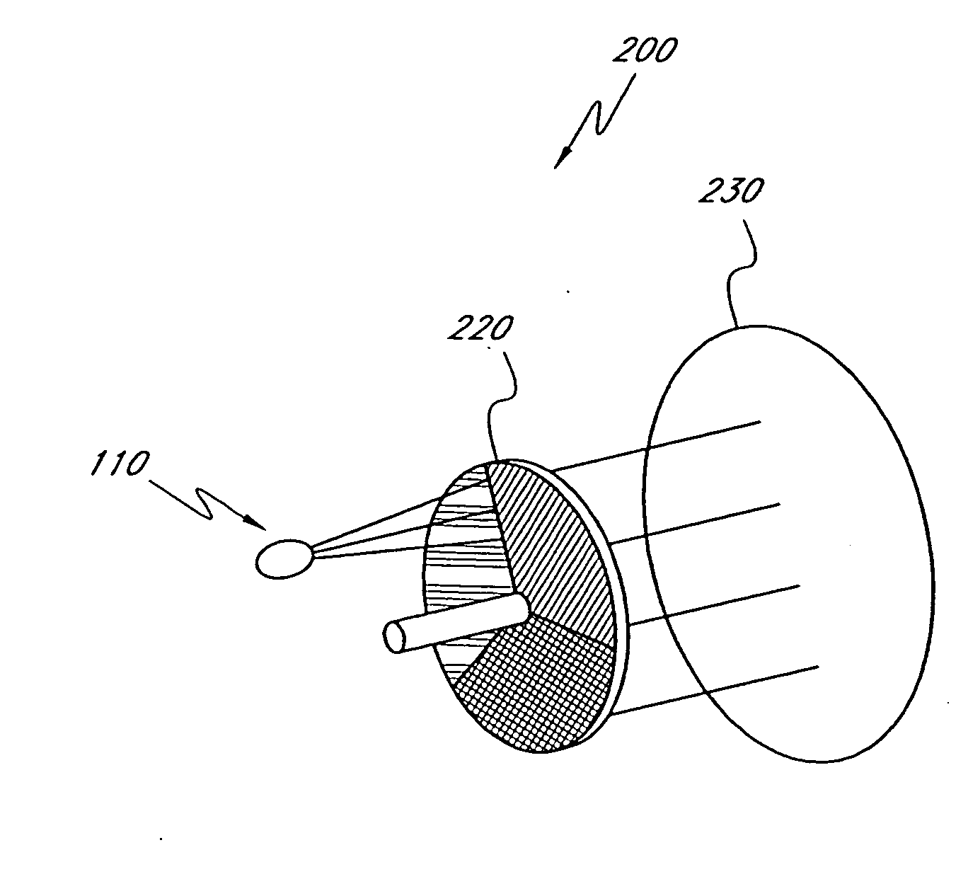
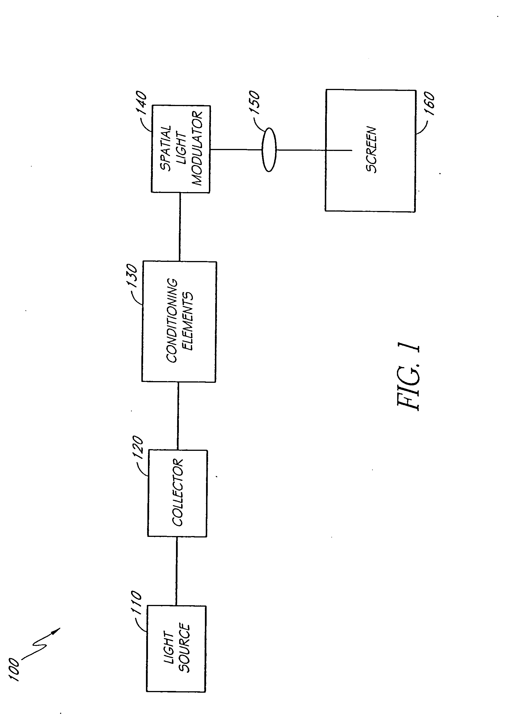
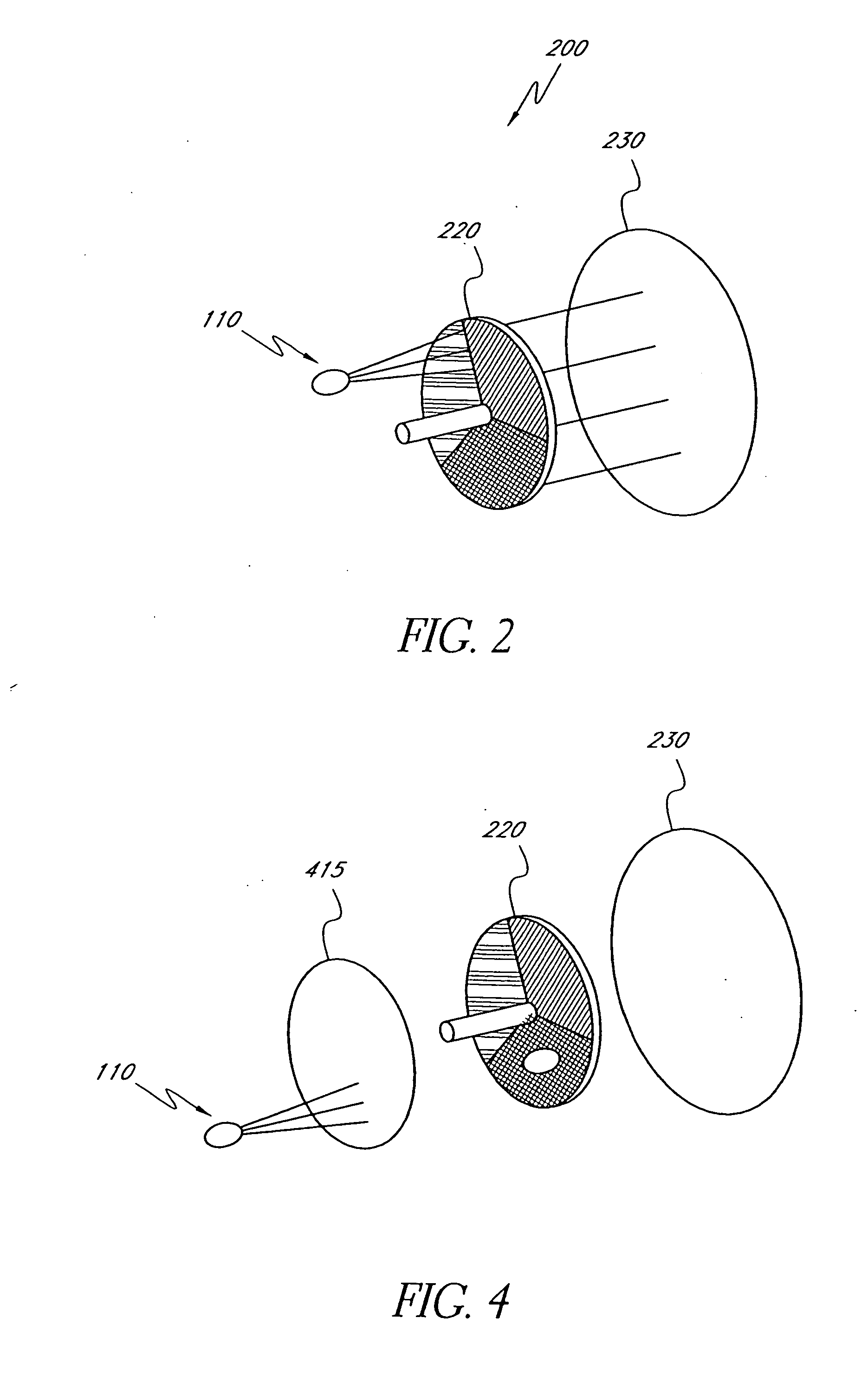
[0021]FIG. 1 is a block diagram of a display apparatus 100. The apparatus 100 includes a light source 110, a collector 120, conditioning elements 130, a spatial light modulator 140, projection optics 150, and a screen 160.

[0022] The collector 120 may comprise one or more lenses that collect and transfer light emitted by the light source 110 to the conditioning elements 130. The conditioning elements 130 may include a variety of one or more light conditioning components, such as mixers and / or other components that condition the light, e.g. increase the homogeneity of the light.

[0023] The spatial light modulator 140 generally includes a plurality of pixels that can be independently activated to produce an image. The modulator 140 can be any of the variety of spatial light modulators known in the art (e.g., DMD, LCD, DLP, LCOS, or GLV) or yet to be developed. The projection optics 150 may comprise one or more optical lenses or elements that can be used to project an image formed by t...


PUM


Abstract

Various embodiments described herein comprise illuminators comprising a phosphor color wheel for producing colored light. Light of a first wavelength emitted by a light source is incident on a phosphor color wheel comprising a plurality of different regions, where at least one of these regions comprises a phosphor that fluoresces at a second wavelength when illuminated with light of the first wavelength. The light from the light source and the different regions of the phosphor color wheel are movable with respect to each other such that as the different regions are illuminated by the light, different colors are produced.

Description

CROSS-REFERENCE TO RELATED APPLICATIONS [0001] This application claims priority under 35 U.S.C. § 120(e) to U.S. Provisional Application Ser. No. 60 / 688196 filed on Jun. 7, 2006 and entitled “Phosphor Wheel Illuminator”, which is incorporated herein by reference in its entirety.BACKGROUND [0002] 1. Field of the Invention [0003] Certain embodiments disclosed herein relate generally to the field of illuminators and more particularly to phosphor wheel illuminators for use, for example, in display systems. [0004] 2. Description of the Related Art [0005] It is common practice in some projection display systems to use one or more white light sources in combination with filter color wheels to produce a full color image. A typical color wheel is made up of a series of color filters such as absorption filters or interference filters. Color light is produced by passing white light produced by the white light source through the color filters to create a colored light. A full color image is pro...

Claims


Application Information

Patent Timeline
Patent Type & Authority Applications(United States)
IPC IPC(8): F21V9/00F21V9/40
CPCF21S10/007F21S10/02F21V9/10G02B6/0066F21V9/14G03B21/204H04N9/3114H04N9/315G02B26/008F21V9/32F21V9/45F21V13/14
Inventor MCGUIRE, JAMES P. JR.CASSARLY, WILLIAM J.
Owner SYNOPSYS INC
Why Eureka
Try Eureka