Eureka AIR delivers breakthrough ideas for toughest innovation challenges, trusted by R&D personnel around the world.

Light source unit and projector

a technology of light source unit and projector, which is applied in the direction of instruments, discharge tubes, luminescnet screens, etc., can solve the problems of affecting the life of the components on which ultraviolet light is reflected, and ensuring the long life of the optical components becomes difficul

Active Publication Date: 2009-11-19
CASIO COMPUTER CO LTD
View PDF13 Cites 258 Cited by
  • Summary
  • Abstract
  • Description
  • Claims
  • Application Information

AI Technical Summary

Benefits of technology

[0008]The problem that the invention is to solve is to provide a light source unit which can maintain its performance over a long period of time by suppressing the deterioration with age of an optical component on to which excitation light is shone and a projector including the light source unit.

Problems solved by technology

However, since the proposed light source unit by Japanese Unexamined Patent Publication No. 2004-341105 employs the excitation light source which uses ultraviolet light with high energy as excitation light, the optical component on to which ultraviolet light is shone is liable to be damaged, leading to a problem that ensuring a long life for the optical component becomes difficult.

Method used


Image

  • Light source unit and projector
  • Light source unit and projector
  • Light source unit and projector

Examples


Embodiment Construction

[0020]Hereinafter, a best mode for carrying out the invention will be described by the use of the accompanying drawings. However, while various limitations which are technically preferred to carry out the invention are given to an embodiment which will be described below, it should be noted that the scope of the invention be limited to neither the following embodiment nor illustrated examples.

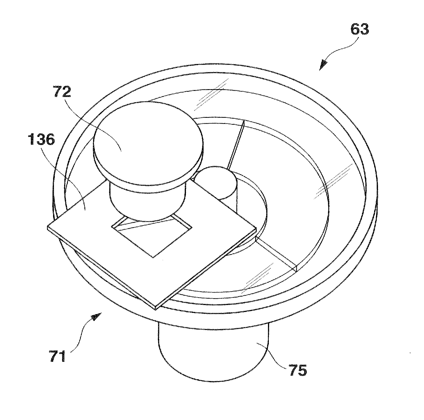
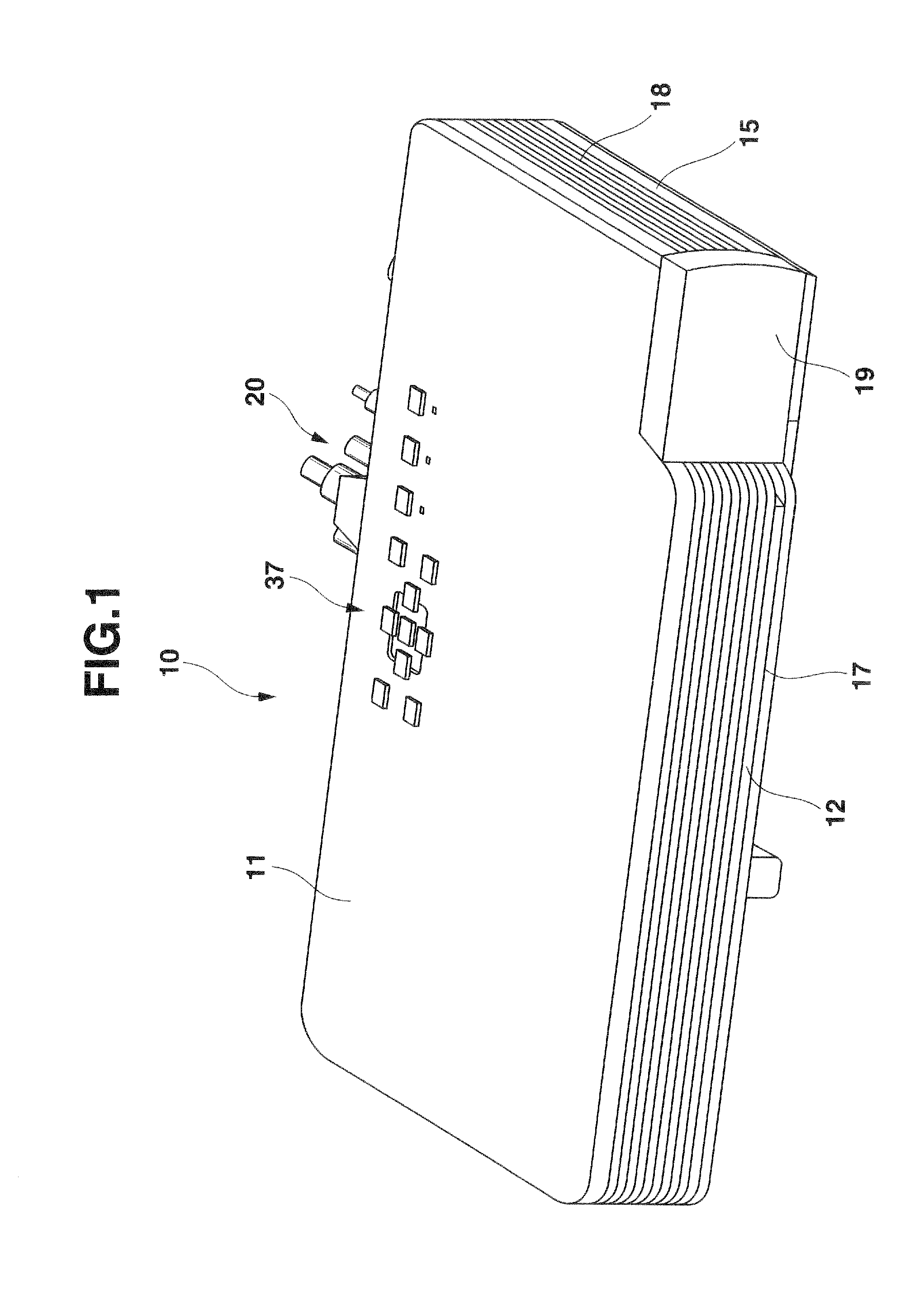
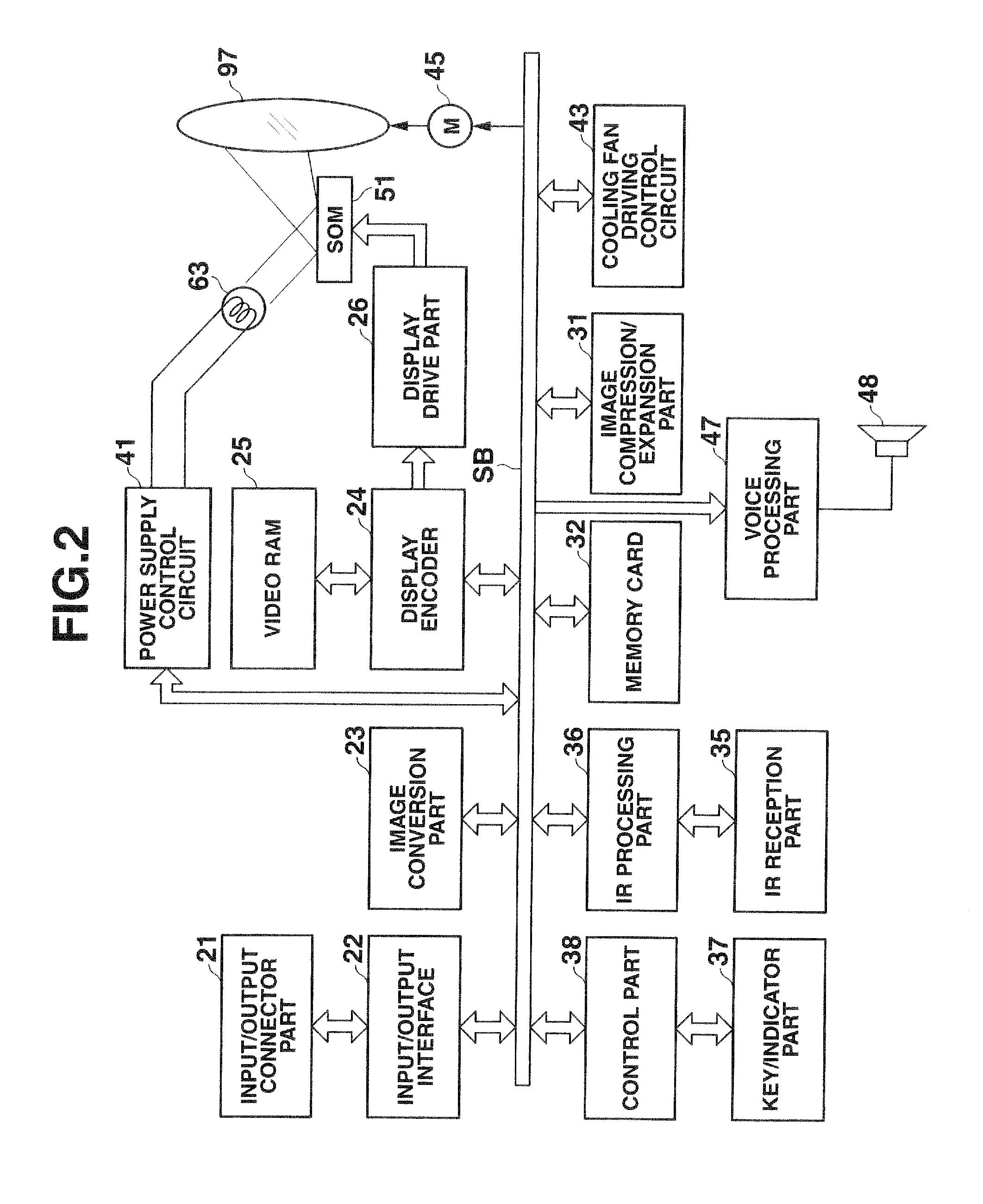
[0021]A projector 10, which is a best mode for carrying out the invention, includes a light source unit 63, a display device 51, a cooling fan, a light source side optical system 61 for guiding light from the light source unit 63 to the display device 51, a projection side optical system 62 for projecting an image emitted from the display device 51 on to a screen and a projector control unit for controlling the light source unit 63 and the display device 51.

[0022]In addition, this light source unit 63 has a plurality of fan-shaped segment areas on a circular transparent base material 130 which ...


PUM


Abstract

A projector comprises a light source unit 63, a display device, a cooling fan, a light source side optical system for guiding light from the light source unit 63 to the display device, a projection side optical system for projecting an image emitted from the display device on to a screen, and a projector control unit for controlling the light source unit 63 and the display device. In addition, this light source unit 63 has a plurality of fan-shaped segment areas on a circular transparent base material 130 which can be controlled to rotate, layers 131 of different phosphors which emit light of predetermined wavelength bands by receiving excitation light being disposed on at least two of the segment areas on the transparent base material 130, and comprises an excitation light source 72 which shines excitation light within a visible light wavelength band on to the phosphors.

Description

CROSS-REFERENCE TO RELATED APPLICATIONS[0001]This application is based upon and claims the benefit of priority under 35 USC 119 of Japanese Patent Application No. 2008-127947 filed on May 15, 2008, the entire disclosure of which, including the description, claims, drawings, and abstract, is incorporated herein by reference in its entirety.BACKGROUND OF THE INVENTION[0002]1. Field of the Invention[0003]The present invention relates to a light source unit and a projector which incorporates the light source unit.[0004]2. Description of the Related Art[0005]In these days, projectors are used in many cases as an image projection apparatus for projecting screens and video images of a personal computer and, further, images based on image data stored in a memory card on to a screen. In projectors of this type, light emitted from a light source is concentrated on to a micromirror display device referred to as a DMD (Digital Micromirror Device) or a liquid crystal panel so as to display a col...

Claims


Application Information

Patent Timeline
IPC IPC(8): H01J1/62F21V9/40
CPCF21V9/10G02B7/006G02B26/008G03B21/16G03B21/204H04N9/3114H04N9/3197G02B27/1073F21V9/45G03B21/14G02B5/26G03B21/00
Inventor IWANAGA, MASAKUNI
Owner CASIO COMPUTER CO LTD
Why Eureka
Eureka Blog
Learn More