
Illumination devices comprising white light emitting diodes and diode arrays and method and apparatus for making them

a technology of light-emitting diodes and illumination devices, which is applied in the direction of basic electric elements, semiconductor devices, electrical equipment, etc., can solve the problems of difficult control, difficult to efficiently make white leds enough to compete with conventional light sources, and widen the effective optical area

Active Publication Date: 2005-10-13
LIGHTING SCI GROUP
View PDF39 Cites 250 Cited by
  • Summary
  • Abstract
  • Description
  • Claims
  • Application Information

AI Technical Summary

Benefits of technology

[0009] The white LED or LED array can advantageously be fabricated by providing a substrate including one or more LEDs, applying a thin layer of tacky adhesive over the LEDs and applying a thin layer comprising particles of phosphor over the adhesive. The particles adhere to the tacky adhesive...

Problems solved by technology

Unfortunately, it is difficult to efficiently make white LEDs enough to compete with conventional light sources.
One source of inefficiency is coating the LED with the optimal thickness of phosphor.
There are, however, two problems with this approach.
First, the uniformity of the phosphor coating is dependent on the shape of the transparent layer which, in turn, is difficult to control, especially when the resin is dispensed and dried over a wire bonded array.
Second, the presence of the intervening transparent layer separates the LED from the phosphor, causing an undesirable broadening of the effective optical area.
The multiple masking and coating steps add substantially to the time and cost of fabrication.

Method used


Image

  • Illumination devices comprising white light emitting diodes and diode arrays and method and apparatus for making them
  • Illumination devices comprising white light emitting diodes and diode arrays and method and apparatus for making them
  • Illumination devices comprising white light emitting diodes and diode arrays and method and apparatus for making them

Examples


example 1

[0040] Substrate Material: Copper Molybdenum Copper (Sumitomo Inc.)LED: UltraBrightTM InGaN LED (Cree Inc.)First Optical Material: NYOGEL OKT-0451 2 part silicone heat curable (NYE optical)Frequency Converting Material: YAG:Ce Phosphor (Phosphor Technologies UK)Second Optical Material: LED Encapsulant 9616 Dymax Corp

example 2

[0041] Substrate Material: Copper Tungsten (Marketech Int. INC) LED: InGaN / GaN Blue LED's 3.3 (Epistar Corporation)First Optical Material: Sylguard—2 part silicone heat curable (Dow Corning INC)Frequency Converting Material: YAG:Gd Phosphor (Phosphor Tech. USA)Second Optical Material: LS-6257 Encapsulant (Light Span Corp)

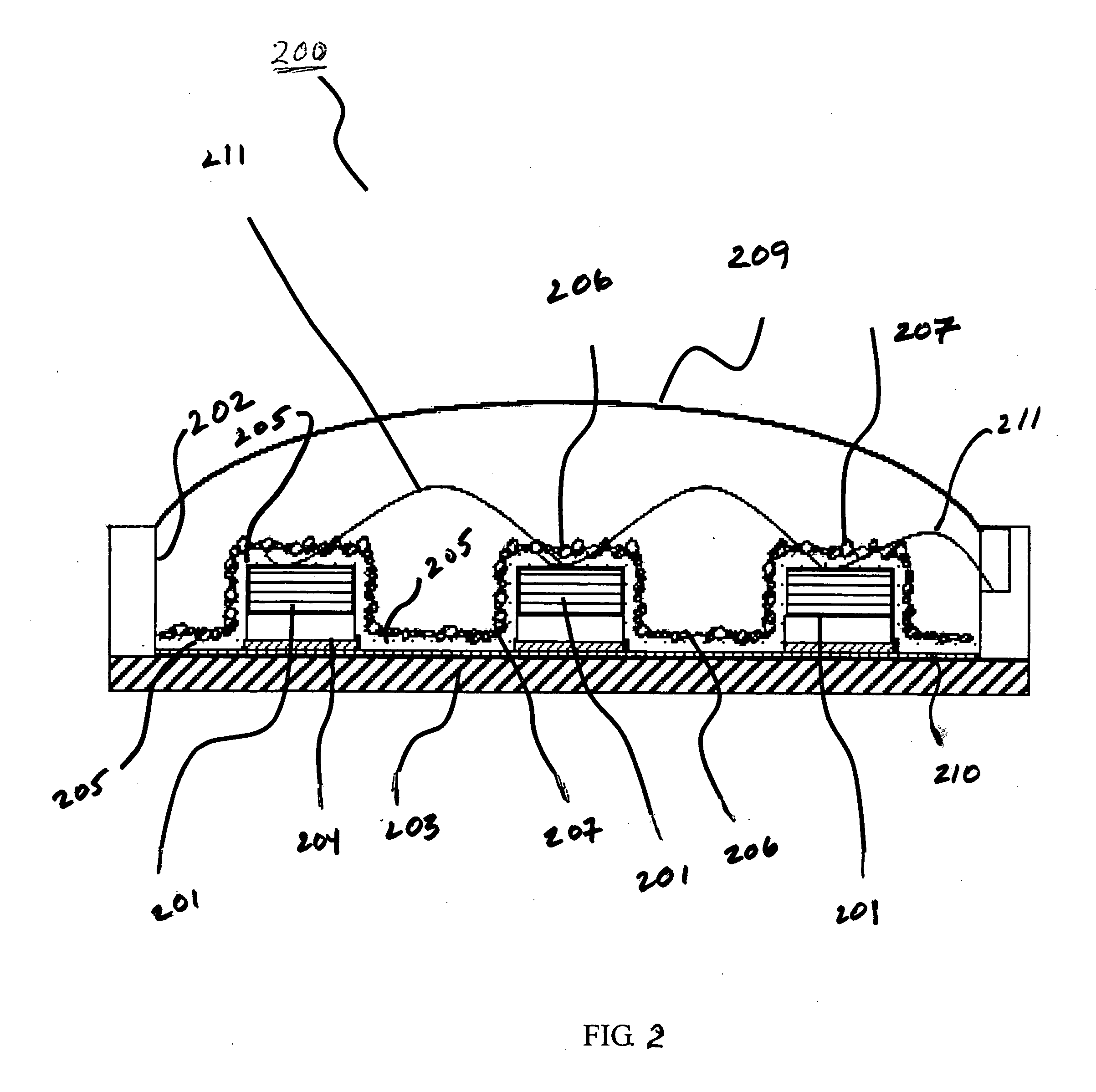
[0042] The advantages of the inventive illumination devices and method are manyfold. An array of LEDs plus a mono-layer of fluorescent material can be used to create a light source having a uniform white light distribution, thus minimizing the “Halo Effect”. Without wishing to be bound by theory, it is believed that the “Halo Effect” or bleed-through effect occurs because the light from the blue LED is directional while the yellow / amber from the phosphor radiates over 2π solid angle. Thus, an observer looking at a prior art LED from the side, can see a color that appears multi-color, not white. The single layer of fluorescent material as per the inventive technique...


PUM


Abstract

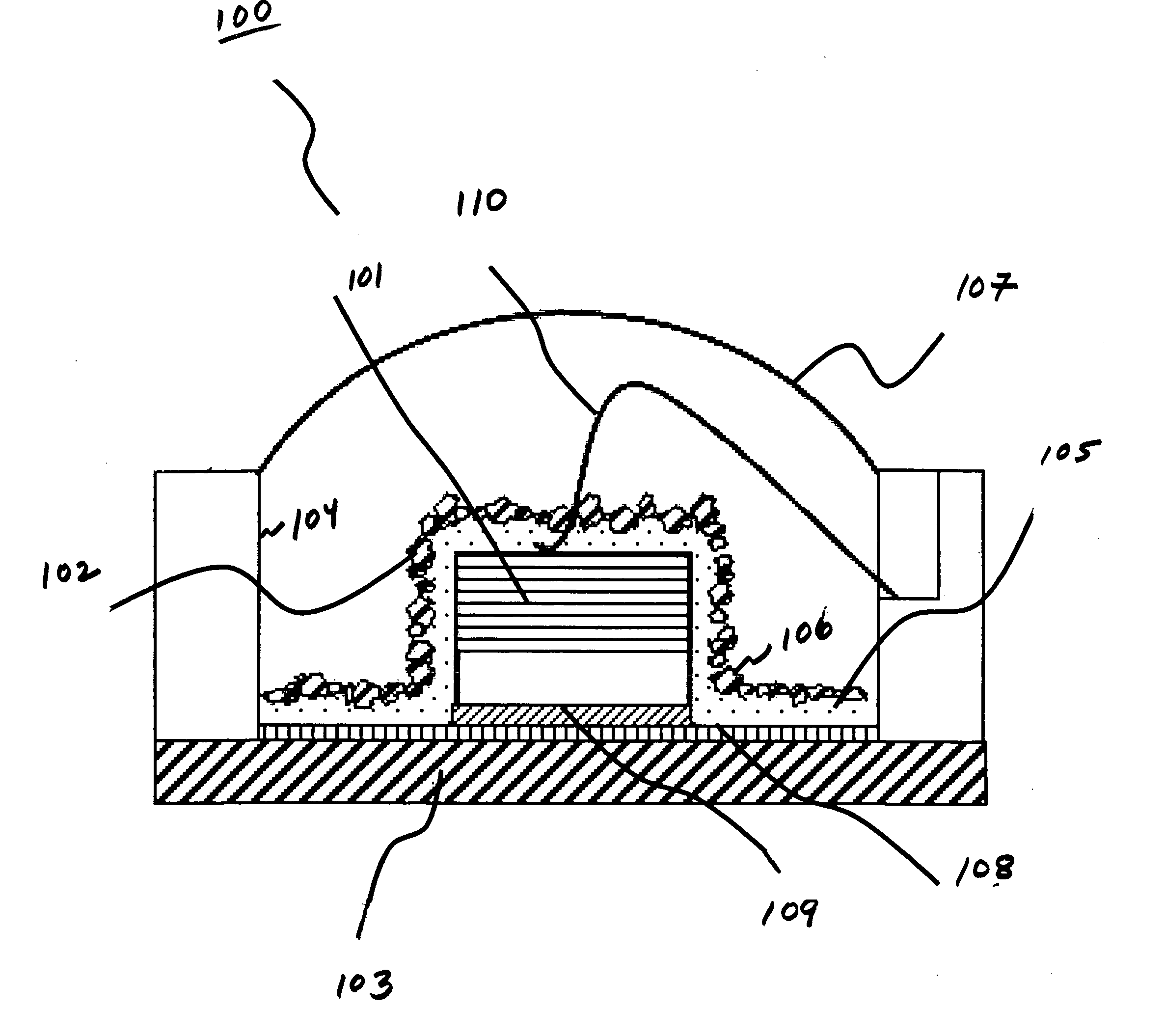
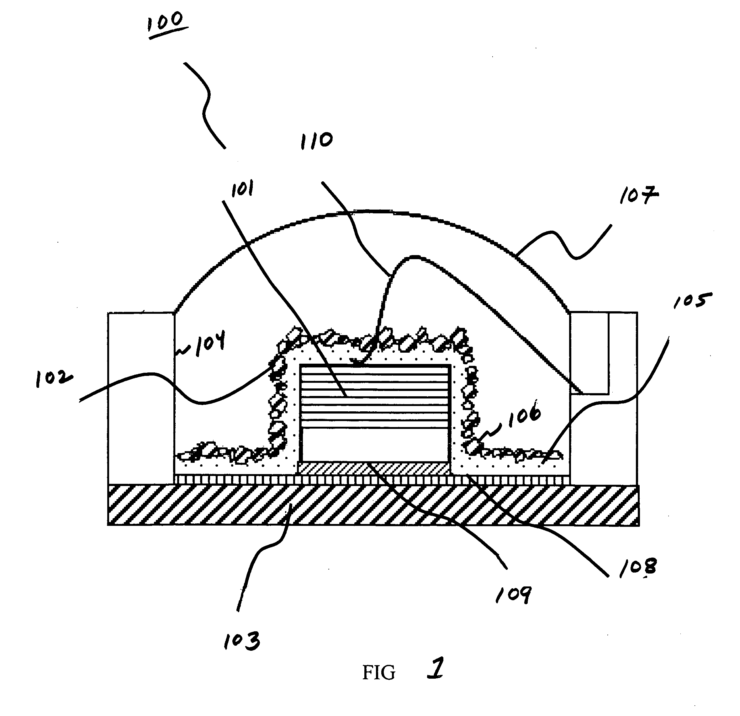
In accordance with the invention, an illumination device comprises a substrate having a surface and a cavity in the surface. At least one light emitting diode (“LED”) is mounted within the cavity, and a monolayer comprising phosphor particles overlies the LED. The phosphor monolayer is adhered to the LED by a monolayer of transparent adhesive material. An optional optical thick layer of transparent material overlies the phosphor monolayer to encapsulate the LED and optionally to form a lens. Methods and apparatus for efficiently making the devices are disclosed.

Description

FIELD OF THE INVENTION [0001] This invention relates to the illumination devices comprising white light emitting diodes (“white LEDs”). BACKGROUND OF THE INVENTION [0002] White LEDs are important in a wide variety of direct and indirect illumination applications. A white LED typically comprises a blue or ultraviolet LED whose emitted light is passed through a phosphor that converts the emitted light to white light. Such LEDs individually or in arrays can be used for room and space illumination, vehicle headlights, signs, and indicators. The emission spectra and color temperature of white LEDs is closer to sunlight than many forms of conventional lighting. [0003] Unfortunately, it is difficult to efficiently make white LEDs enough to compete with conventional light sources. One source of inefficiency is coating the LED with the optimal thickness of phosphor. There should be sufficient phosphor to convert the emitted light but not so much as to block or absorb the white light output. ...

Claims


Application Information

Patent Timeline
IPC IPC(8): H01L25/075H01L33/50
CPCH01L25/0753H01L33/507H01L2933/0041H01L2224/45124H01L2924/00H01L2224/48137H01L2224/8592H01L2924/181H01L2924/00012
Inventor BLONDER, GREG E.AMAYA, EDMAR M.
Owner LIGHTING SCI GROUP
Learn More