
Anti-rotational abutment screw cap and a method for using the same

a technology of anti-rotational abutment and screw cap, which is applied in the field of anti-rotational abutment screw cap and a method for using the same, can solve the problems of loosing the abutment screw, affecting the treatment effect of patients,

Inactive Publication Date: 2012-03-01
OCHENRIDER DAVID MICHAEL
View PDF1 Cites 3 Cited by
  • Summary
  • Abstract
  • Description
  • Claims
  • Application Information

AI Technical Summary

Problems solved by technology

One problem of dental implant use may be the problem of loosening of the abutment screw over time under occlusal loads.
Accessing the abutment screw, and removing or tightening the abutment / prosthesis complex presents significant challenges to the dentist.
The torque wrench driver may place significant stress on the complex, leading to fracture of the prosthesis.
These abutment screw caps, however, require modifications to the generally used abutments and to standard abutments screws, or have complicated designs with moving parts.

Method used


Image

  • Anti-rotational abutment screw cap and a method for using the same
  • Anti-rotational abutment screw cap and a method for using the same
  • Anti-rotational abutment screw cap and a method for using the same

Examples


Embodiment Construction

[0016]The following detailed description is of the best currently contemplated modes of carrying out exemplary embodiments of the invention. The description is not to be taken in a limiting sense, but is made merely for the purpose of illustrating the general principles of the invention, since the scope of the invention is best defined by the appended claims.

[0017]Various inventive features are described below that can each be used independently of one another or in combination with other features.

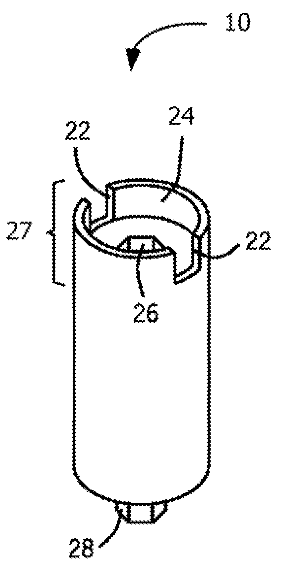
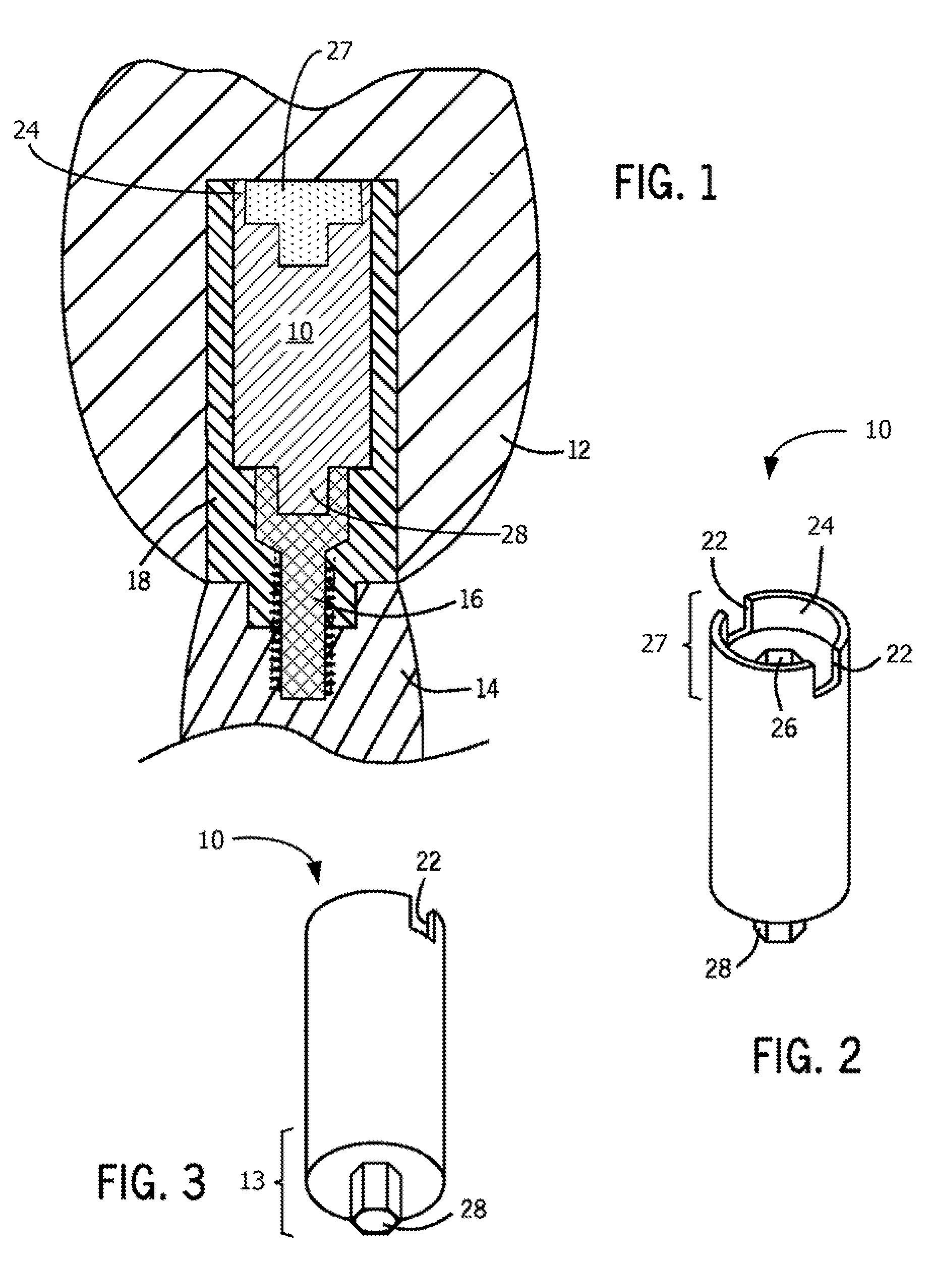
[0018]Broadly, an embodiment of the present invention generally provides an anti-rotational abutment screw cap (ARASC) for use in dental implants.

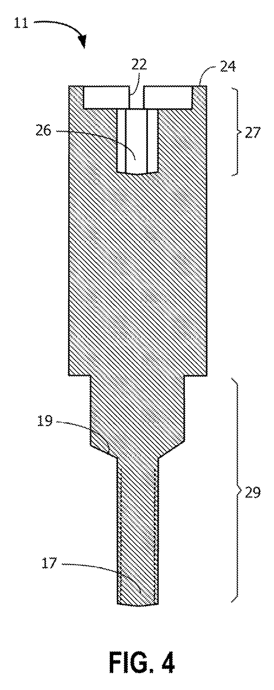
[0019]Referring now to FIGS. 1-3, different views of the ARASC 10 are shown according to an exemplary embodiment of the present invention. The ARASC 10 may be a single piece device. The ARASC 10 may have a cylindrical shaped body, and its size may depend on the size of an abutment 18. The ARASC 10 may be formed with two functional end portions. A...


PUM


Abstract

An anti-rotational abutment screw cap includes a generally cylindrical-shaped body, the cylindrical-shaped body having a socket-end portion and an insert-end portion; a blind recess socket located on an end of the socket-end portion for receiving a torque wrench driver, the blind recess socket having an interior configuration; a retentive edge formed above and around the blind recess socket for engaging prosthetic cement; an insert key protruding from an end of the insert-end portion for engaging a head opening of an abutment screw, the insert key having an exterior configuration which generally mating with the interior configuration of the blind recess socket.

Description

CROSS-REFERENCE TO RELATED APPLICATION[0001]The present application claims the benefit under 35 U.S.C. §119(e) of U.S. Provisional Application No. 61 / 379,290, filed Sep. 1, 2010, which is incorporated herein by reference.BACKGROUND OF THE INVENTION[0002]Current dental implant systems generally include three components, an implant body, an abutment, and an abutment screw. A prosthesis, such as a crown, may be supported by said implant system. The abutment may be attached to the implant body with an abutment screw. One problem of dental implant use may be the problem of loosening of the abutment screw over time under occlusal loads. Accessing the abutment screw, and removing or tightening the abutment / prosthesis complex presents significant challenges to the dentist.[0003]The current dental implant protocol recommends “protecting” the abutment screw head from prosthetic cement with materials such as a cotton pellet or temporary filling material. The recommended “protection” provides n...

Claims


Application Information

Patent Timeline
IPC IPC(8): A61C8/00
CPCA61C8/005A61C8/008A61C8/0063
Inventor OCHENRIDER, DAVID MICHAEL
Owner OCHENRIDER DAVID MICHAEL
Learn More