
Sanitary tampon

a technology of sanitary tampon and absorbent pad, which is applied in the field of sanitary tampon, can solve the problems of menstrual blood, worsen the ability of the absorber and sanitary tampon, and achieve the effect of improving the ability to absorb body fluids and preventing the stick to the vaginal wall

Inactive Publication Date: 2012-03-01
UNI CHARM CORP
View PDF10 Cites 9 Cited by
  • Summary
  • Abstract
  • Description
  • Claims
  • Application Information

AI Technical Summary

Benefits of technology

[0006]A way to improve the ability of the absorber to absorb body fluids is to make the surface of the absorber hydrophilic. However, if the surface of the absorber is made hydrophilic, the absorber excessively absorbs body fluids existing on the vaginal wall surface. This causes a phenomenon that the surface of the absorber sticks to the vaginal wall. Such phenomenon increases the frictional resistance generated when the sanitary tampon is inserted or taken out after use, which causes a user to feel uncomfortable.
[0007]Accordingly, an object of the present invention is to provide a sanitary tampon having an improved ability to absorb body fluids such as menstrual blood and being prevented from sticking to a vaginal wall.
[0009]According to the present invention, it is possible to provide a sanitary tampon having an improved ability to absorb body fluids such as menstrual blood and being prevented from sticking to a vaginal wall.

Problems solved by technology

However, the above-described conventional sanitary tampon has the following problem.
Specifically, having hydrophobic properties, the surface of the absorber (the liquid-permeable layer) to come into contact with a vaginal wall worsens the ability of the absorber to absorb body fluids such as menstrual blood.
For this reason, the body fluids tend to easily flow on the surface of the absorber, thus sometimes causing leakage of the menstrual blood and wearing discomfort.
However, if the surface of the absorber is made hydrophilic, the absorber excessively absorbs body fluids existing on the vaginal wall surface.
Such phenomenon increases the frictional resistance generated when the sanitary tampon is inserted or taken out after use, which causes a user to feel uncomfortable.

Method used


Image

  • Sanitary tampon
  • Sanitary tampon
  • Sanitary tampon

Examples


first embodiment

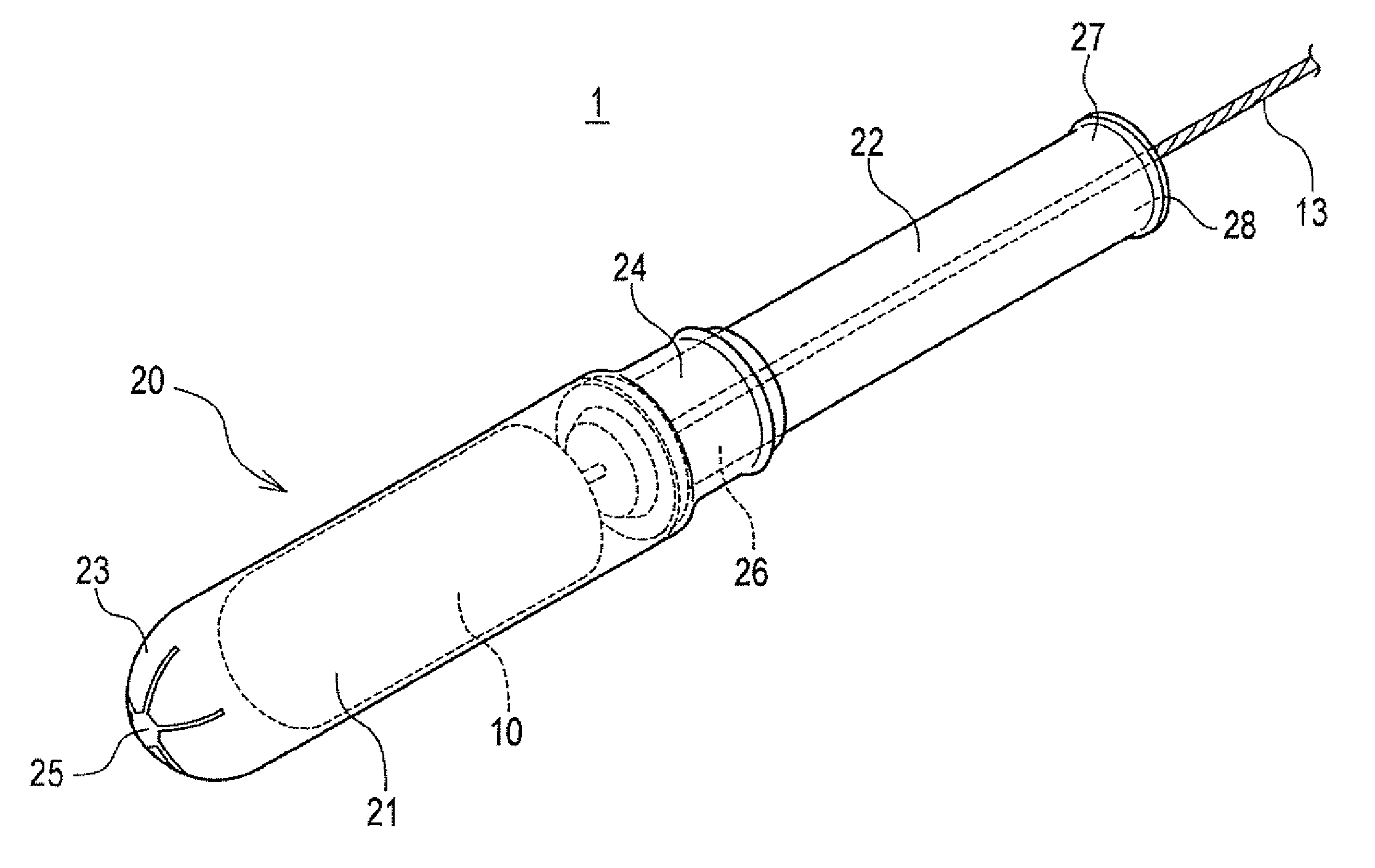
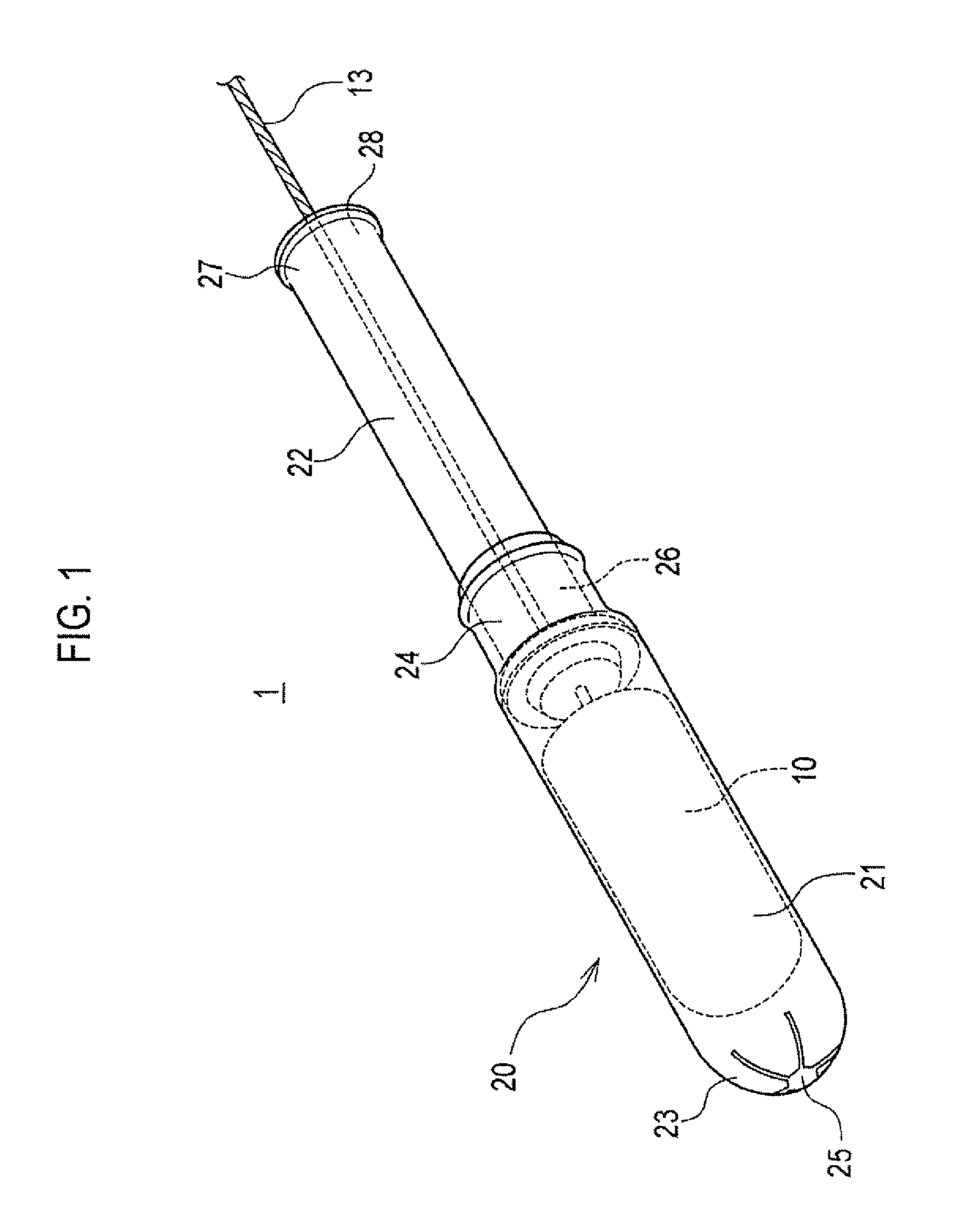
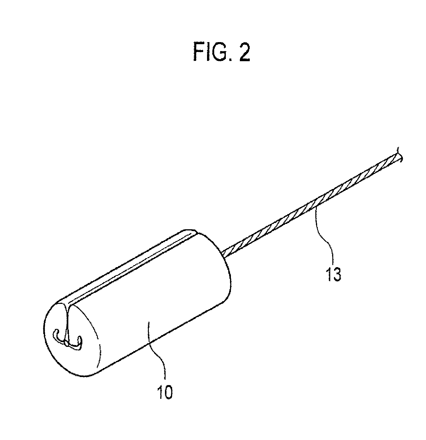
[0021]FIG. 1 is a perspective view of a sanitary tampon 1. The sanitary tampon 1 includes an absorber body 10 and an applicator 20 housing the absorber body 10.

[0022]The applicator 20 includes an outer tube 21 housing the absorber body 10 to be electable therefrom and a pushing body 22 pushing the absorber body 10.

[0023]The outer tube 21 includes an outer tube front end 23 which is inserted into the vagina of a user and an outer tube rear end 24 which is located opposite to the outer tube front end 23. The outer tube front end 23 has an opening portion 25 through which the absorber body 10 is ejected.

[0024]The pushing body 22 includes a pushing front end 26 which pushes the absorber body 10 toward the outside of the outer tube 21 and a pushing rear end 27 which is located opposite to the pushing front end 26.

[0025]The pushing body 22 has a continuous hole 28 communicating with the pushing front end 26 and the pushing rear end 27. A cord 13 (to be described later) connected with the ...

second embodiment

[0053]A second embodiment of the present invention is described below. In the second embodiment, the structure of a covering member covering an absorber is different from that of the first embodiment. In the following description, portions different from the first embodiment are described. Similar to FIG. 5, FIG. 6 is a partially enlarged view of an absorber and a covering member covering the absorber. In the second embodiment, a covering member 31 is used in place of the covering member 11.

[0054]The covering member 31 includes an inner side surface 31A being in contact with an absorber 12 and an outer side surface 31B to come into contact with a vaginal wall when in use. The covering member 31 includes a hydrophobic fiber 101 with a low affinity to water and a hydrophilic fiber 102 with a high affinity to water. An abundance ratio of the hydrophobic fiber 101 in the outer side surface 31B is higher than that of the hydrophilic fiber 102 in the outer side surface 31B. The inner side...

third embodiment

[0056]A third embodiment of the present invention is described below. In the third embodiment, the structure of a covering member covering an absorber is different from those of the first and second embodiments. In the following description, portions different from the first and second embodiments are described. Similar to FIG. 5, FIG. 7 is a partially enlarged view of an absorber and a covering member covering the absorber. In the third embodiment, a covering member 41 is used in place of the covering member 11.

[0057]The covering member 41 includes an inner side surface 41A being in contact with an absorber 12 and an outer side surface 41B to come into contact with a vaginal wall when in use. The covering member 41 includes a hydrophobic fiber 101 with a low affinity to water and a hydrophilic fiber 102 with a high affinity to water. An abundance ratio of the hydrophobic fiber 101 in the outer side surface 41B is higher than that of the hydrophilic fiber 102 in the outer side surfa...


PUM


Abstract

The covering member includes an inner side surface being in contact with the absorber and an outer side surface to come into contact with a vaginal wall when in use. The covering member contains a hydrophobic fiber with a low affinity to water and a hydrophilic fiber with a high affinity to water. In the outer side surface, an abundance ratio of the hydrophobic fiber is higher than an abundance ratio of the hydrophilic fiber.

Description

TECHNICAL FIELD[0001]The present invention relates to a sanitary tampon including an absorber having an absorbent fiber and a covering member covering the absorber.BACKGROUND ART[0002]A sanitary tampon includes an absorber capable of absorbing body fluids and a covering member covering the absorber, and is inserted into the vagina of a user to absorb body fluids such as menstrual blood.[0003]As such a sanitary tampon, a sanitary tampon including an absorber layer having an absorbent fiber covered with a hydrophobic liquid-permeable layer to form an absorber is known (see, for example, Patent Literature 1).PRIOR ART DOCUMENTPatent Literature[Patent Literature 1][0004]Japanese Patent Application Publication No. No. 2001-8964SUMMARY OF INVENTION[0005]However, the above-described conventional sanitary tampon has the following problem. Specifically, having hydrophobic properties, the surface of the absorber (the liquid-permeable layer) to come into contact with a vaginal wall worsens the...

Claims


Application Information

Patent Timeline
IPC IPC(8): A61F13/20
CPCA61F13/2031A61F13/2071A61F2013/15422A61F13/53708A61F13/51305A61F13/20A61L15/42
Inventor KINOSHITA, AKIEISONO, MASATOYAMAKI, KOICHIWATANABE, HITOSHI
Owner UNI CHARM CORP
Learn More