Apparatus and method for mixing fuel in a gas turbine nozzle

a gas turbine and nozzle technology, applied in the direction of engine ignition, engine starters, lighting and heating apparatus, etc., can solve the problems of increasing the chance of flame flashback, localized hot spots in the combustor near the nozzle exit, and damage to the nozzl

Active Publication Date: 2012-03-08
GENERAL ELECTRIC CO
View PDF6 Cites 34 Cited by
  • Summary
  • Abstract
  • Description
  • Claims
  • Application Information

AI Technical Summary

Problems solved by technology

However, if the fuel and air are not evenly mixed prior to combustion, localized hot spots may exist in the combustor near the nozzle exits.
The localized hot spots increase the chance for flame flash back and flame holding to occur which may damage the nozzles.
The localized hot spots may also increase the generation of oxides of nitrogen, carbon monoxide, and unburned hydrocarbons, all of which are undesirable exhaust emissions.
Oftentimes, however, the higher reactivity fuel nozzles include multiple mixing tubes that result in a larger differential pressure across the nozzles.
In addition, the higher reactivity fuel nozzles often do not include mixing tubes in the center portion of the nozzles.

Method used


Image

  • Apparatus and method for mixing fuel in a gas turbine nozzle
  • Apparatus and method for mixing fuel in a gas turbine nozzle
  • Apparatus and method for mixing fuel in a gas turbine nozzle

Examples


Embodiment Construction

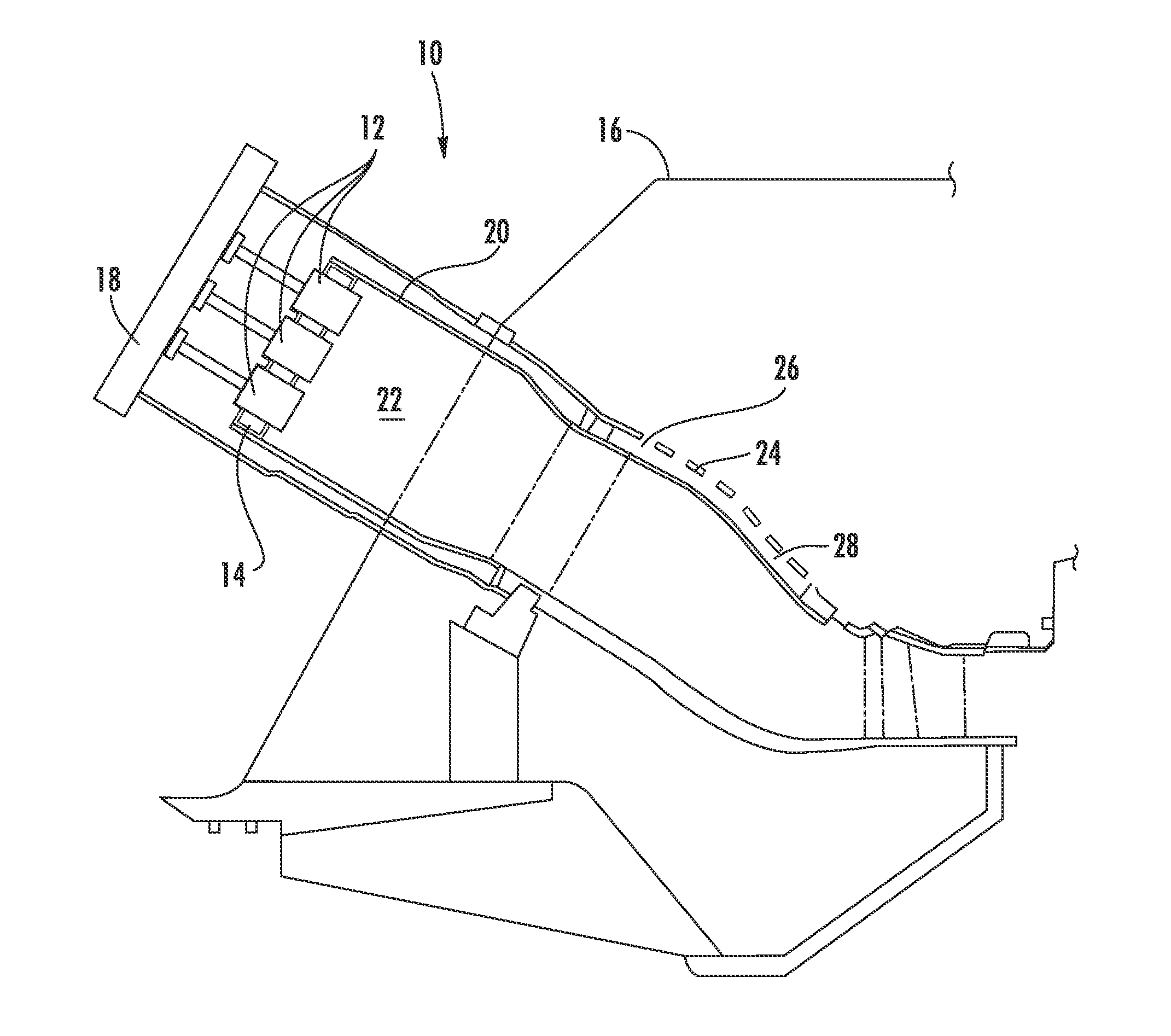
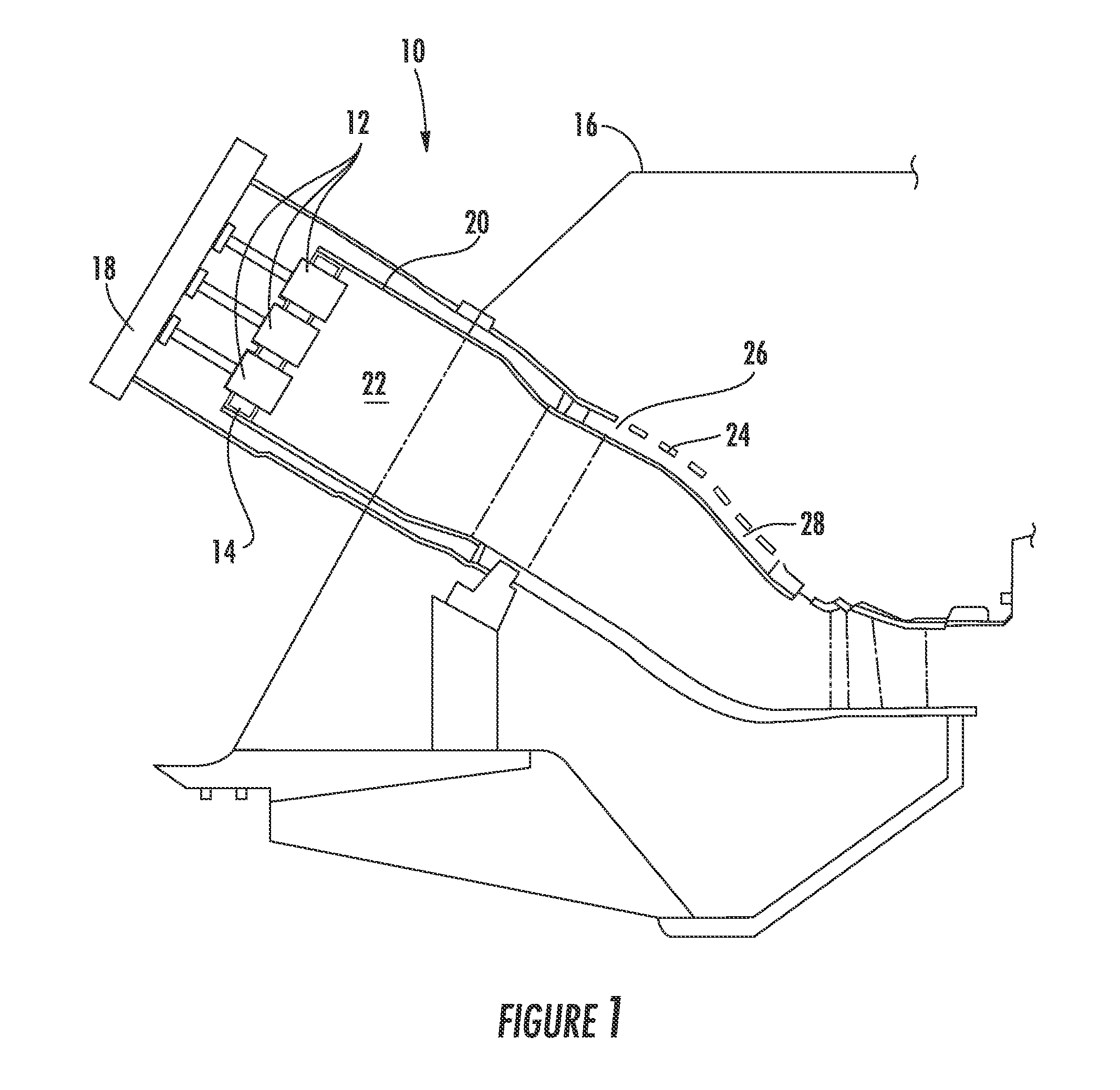
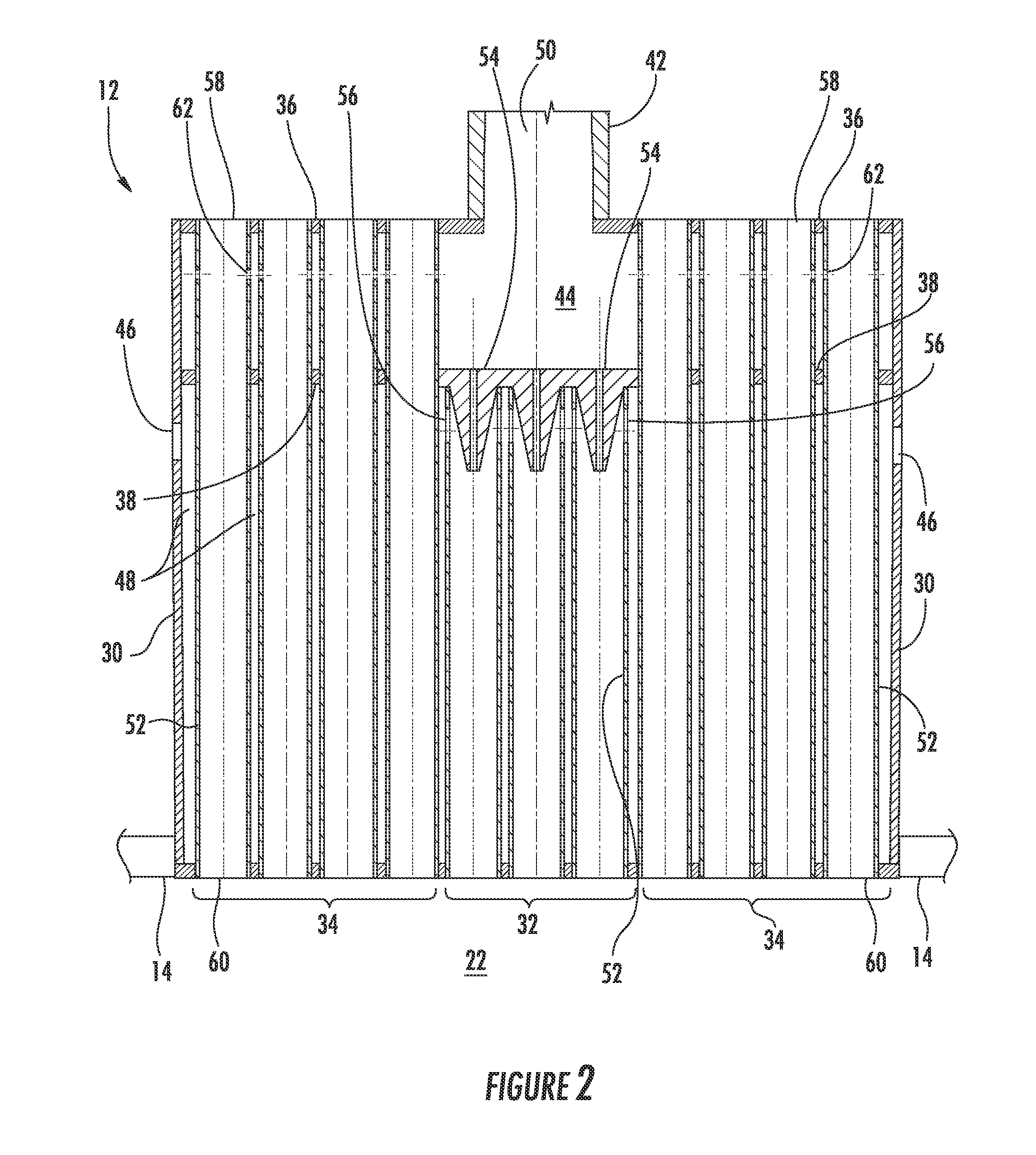
[0020]Reference will now be made in detail to present embodiments of the invention, one or more examples of which are illustrated in the accompanying drawings. The detailed description uses numerical and letter designations to refer to features in the drawings. Like or similar designations in the drawings and description have been used to refer to like or similar parts of the invention.

[0021]Each example is provided by way of explanation of the invention, not limitation of the invention. In fact, it will be apparent to those skilled in the art that modifications and variations can be made in the present invention without departing from the scope or spirit thereof. For instance, features illustrated or described as part of one embodiment may be used on another embodiment to yield a still further embodiment. Thus, it is intended that the present invention covers such modifications and variations as come within the scope of the appended claims and their equivalents.

[0022]Embodiments of...


PUM


Abstract

A nozzle includes a fuel plenum and an air plenum downstream of the fuel plenum. A primary fuel channel includes an inlet in fluid communication with the fuel plenum and a primary air port in fluid communication with the air plenum. Secondary fuel channels radially outward of the primary fuel channel include a secondary fuel port in fluid communication with the fuel plenum. A shroud circumferentially surrounds the secondary fuel channels. A method for mixing fuel and air in a nozzle prior to combustion includes flowing fuel to a fuel plenum and flowing air to an air plenum downstream of the fuel plenum. The method further includes injecting fuel from the fuel plenum through a primary fuel passage, injecting fuel from the fuel plenum through secondary fuel passages, and injecting air from the air plenum through the primary fuel passage.

Description

FEDERAL RESEARCH STATEMENT[0001]This invention was made with Government support under Contract No. DE-FC26-05NT42643, awarded by the Department of Energy. The Government has certain rights in the invention.FIELD OF THE INVENTION[0002]The present invention generally involves an apparatus and method for supplying fuel to a gas turbine. Specifically, the present invention describes a nozzle that may be used to supply fuel to a combustor in a gas turbine.BACKGROUND OF THE INVENTION[0003]Gas turbines are widely used in industrial and power generation operations. A typical gas turbine includes an axial compressor at the front, one or more combustors around the middle, and a turbine at the rear. Ambient air enters the compressor, and rotating blades and stationary vanes in the compressor progressively impart kinetic energy to the working fluid (air) to produce a compressed working fluid at a highly energized state. The compressed working fluid exits the compressor and flows through nozzles...

Claims


Application Information

Patent Timeline
Patent Type & Authority Applications(United States)
IPC IPC(8): F02C7/22
CPCF01D9/023F23R3/005F23R2900/00002F23R3/54F23R3/286
Inventor JOHNSON, THOMAS EDWARDZIMINSKY, WILLY STEVEBERRY, JONATHAN DWIGHT
Owner GENERAL ELECTRIC CO
Why Eureka
Try Eureka