

Centrifugal force pendulum
- Summary
- Abstract
- Description
- Claims
- Application Information
AI Technical Summary
Benefits of technology
Problems solved by technology
Method used
Image

Examples
Embodiment Construction
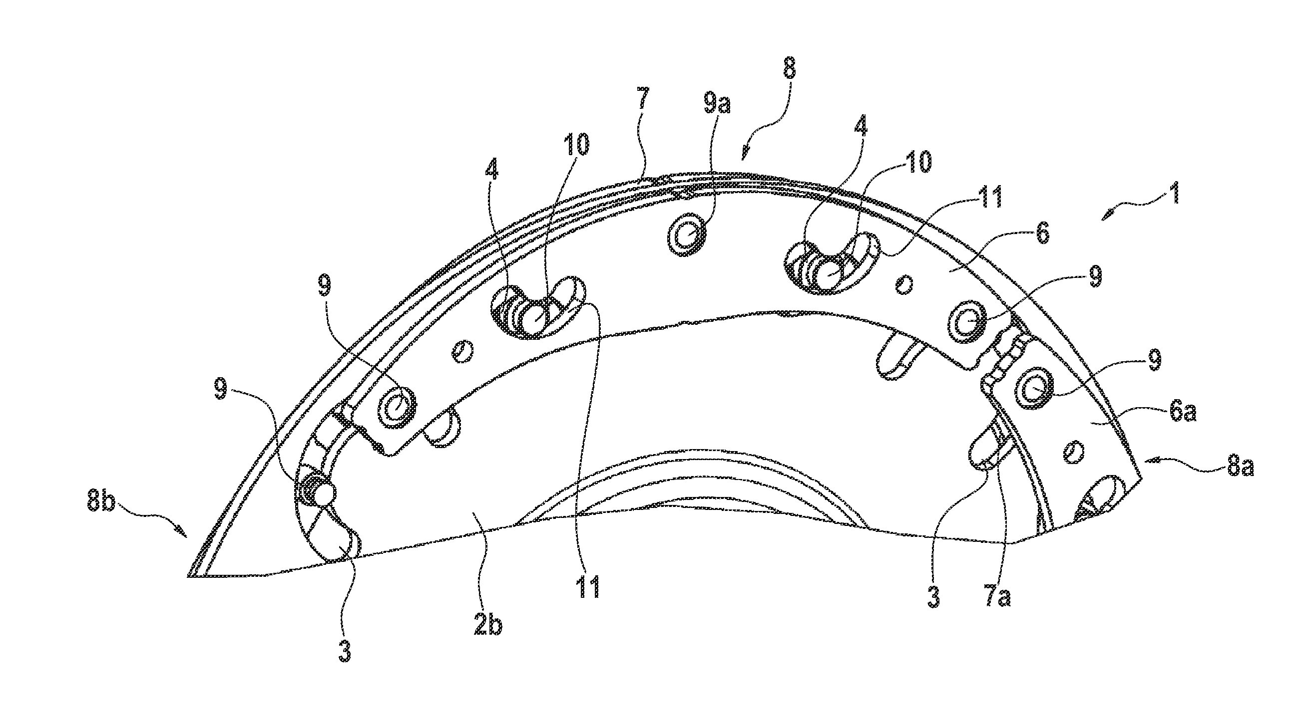
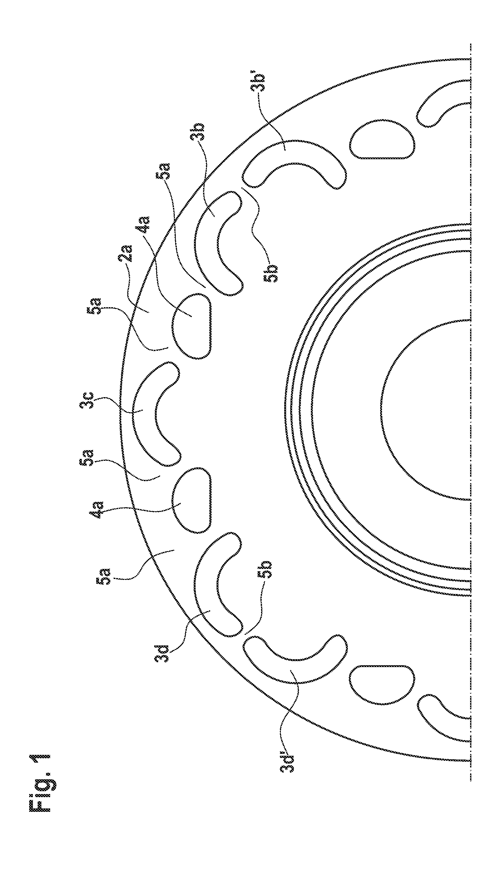
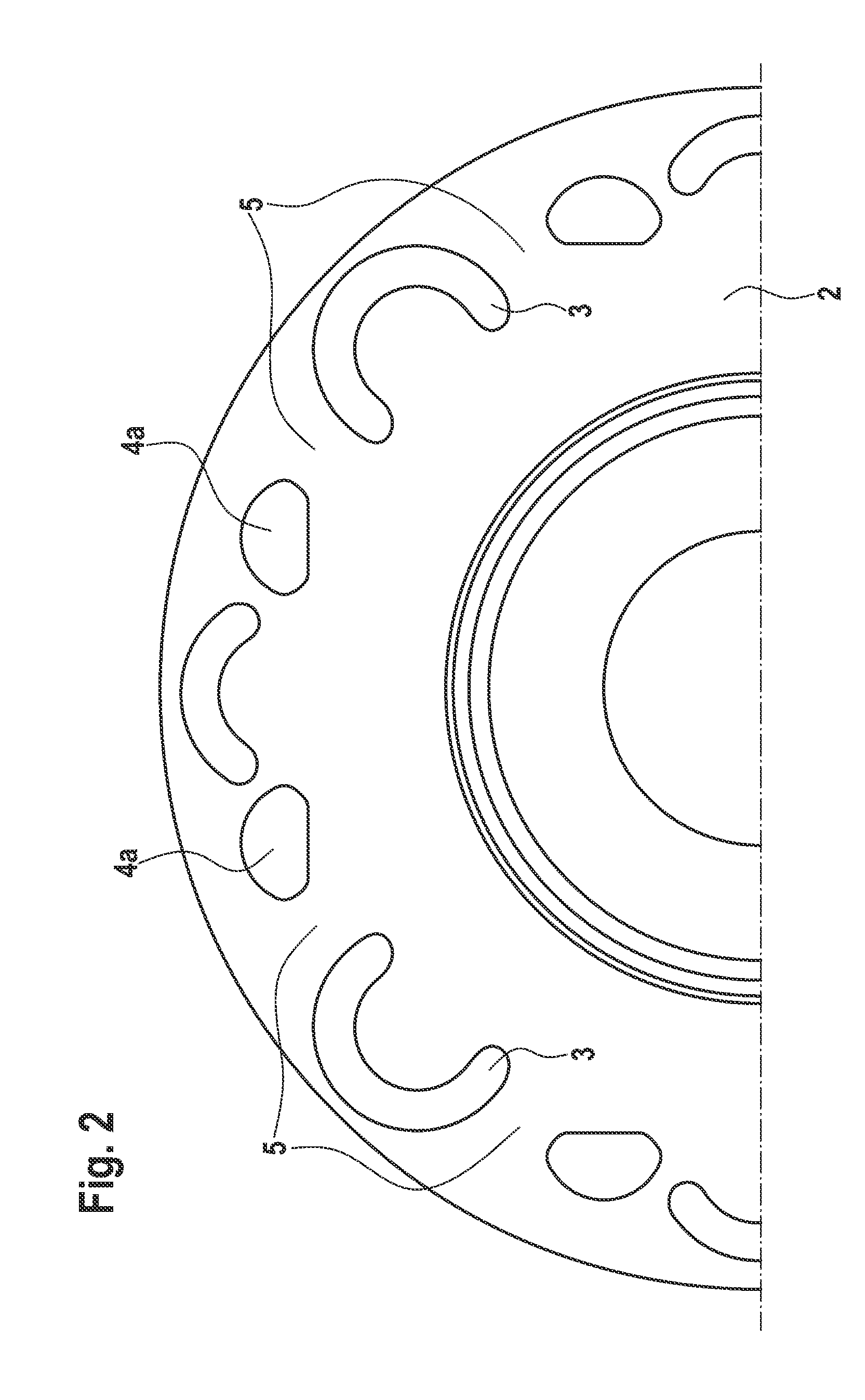
[0018]FIG. 1 illustrates a pendulum flange 2a of a prior art centrifugal force pendulum. Thus, openings 3b, 3c, 3d for the webs are provided, wherein the webs connect two respective axially offset absorber masses which are respectively arranged at one side surface of the pendulum flange 2a and connect them to form a absorber mass pair in that one respective web, e.g., a rivet riveted together with both absorber masses reaches through one respective opening of the openings 3b, 3c and 3d. Thus the shape of the openings 3b, 3c, 3d is predetermined by the possible path of the absorber mass pairs during pivoting relative to the pendulum flange 2a. This path is predetermined by the cutouts 4a and the cutouts which are respectively provided in the absorber masses, wherein a rolling element respectively rolls in the cutouts 4a and the respectively opposite cutouts of the absorber masses. The openings 3b′, 3d′ are the pass through openings for the webs of the adjacent absorber mass pairs.
[00...
PUM
 Abstract
Description
Claims
Application Information