
Downhole valve tool and method of use

Active Publication Date: 2012-03-08
SPECIALISED GASOLINEEUM SERVICES GROUP
View PDF4 Cites 24 Cited by
  • Summary
  • Abstract
  • Description
  • Claims
  • Application Information

AI Technical Summary

Benefits of technology

[0055]In an embodiment of the method, the workstring is a drill string which includes a liner top test tool equipped with means for setting the liner top test tool at the liner top, and the drillstring section incorporating the isolation valve is run in hole dry (i.e. without circulation fluid or mud within it) and closed so that there is no fluid communication with the drill string be

Problems solved by technology

Drilling operations may be hampered if the borehole formed by drilling is unstable.
Since the operation is conducted deep downhole, it is

Method used


Image

  • Downhole valve tool and method of use
  • Downhole valve tool and method of use
  • Downhole valve tool and method of use

Examples


Example

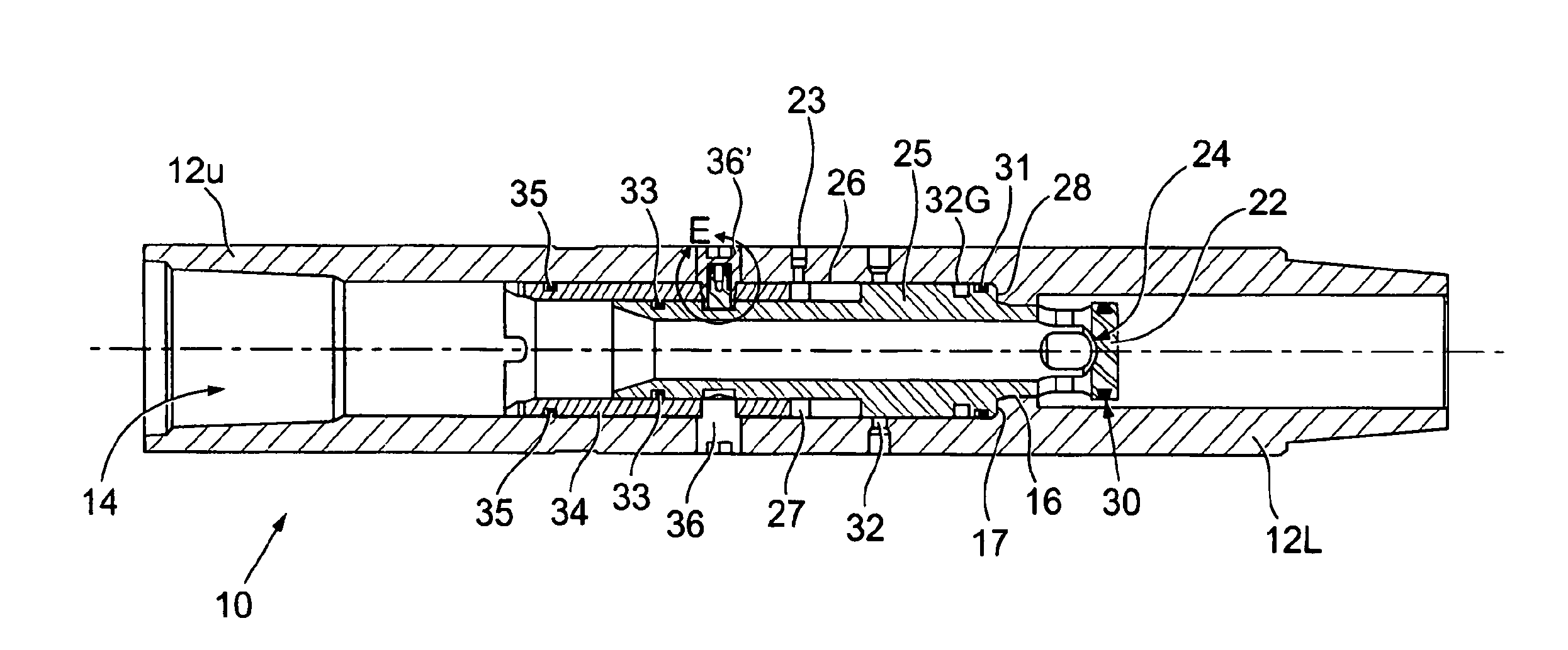
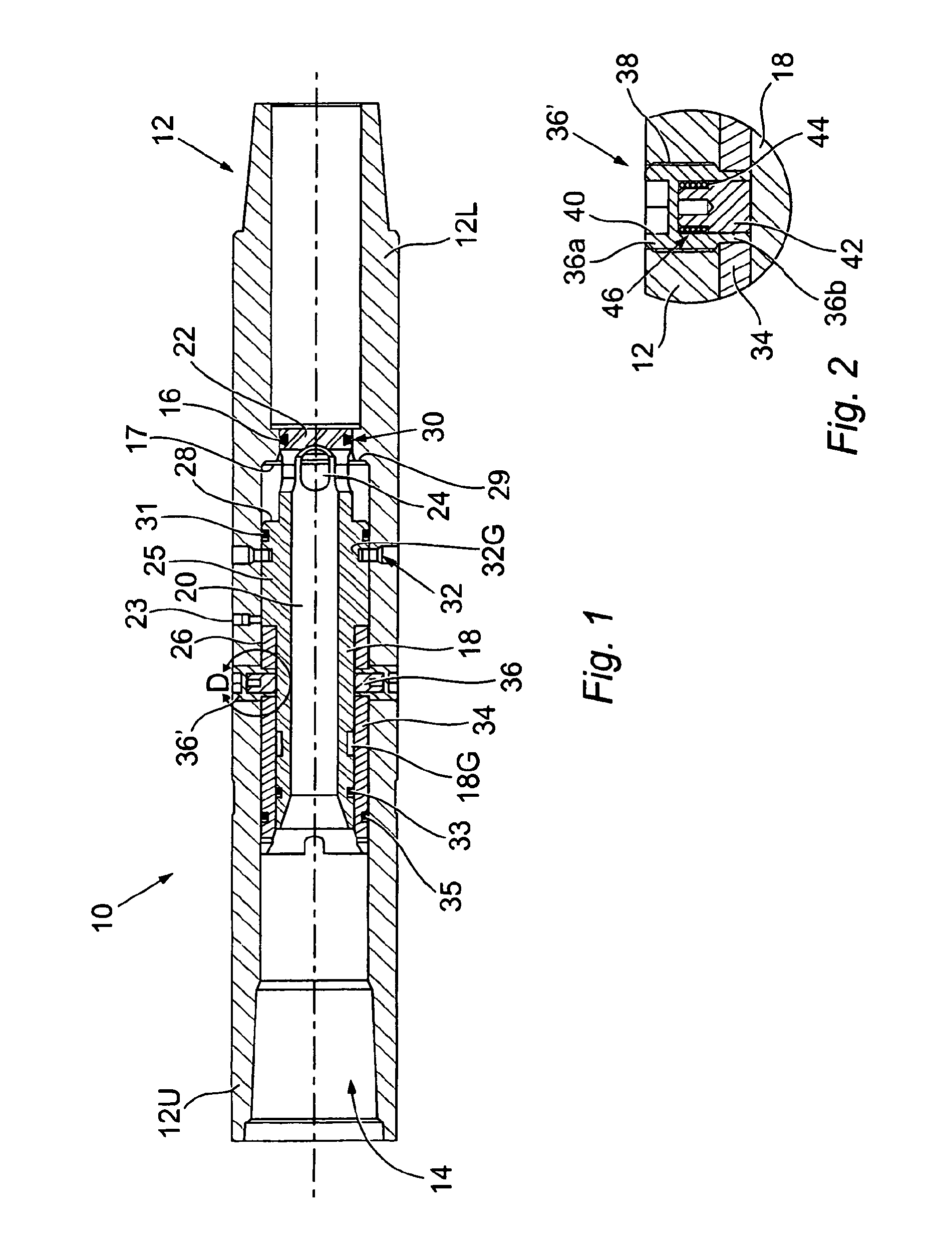
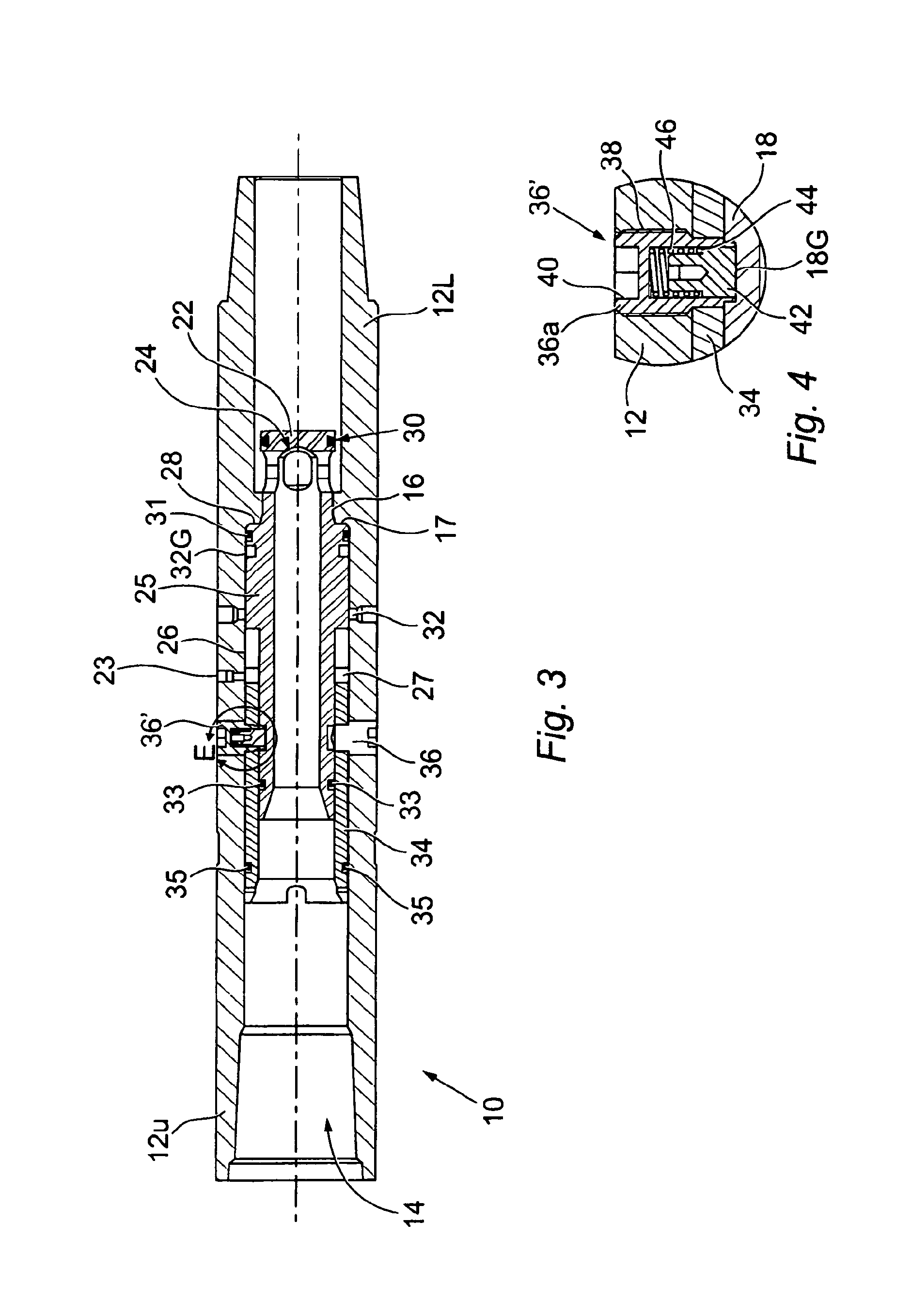
[0064]FIG. 1 shows a tubular isolation valve 10 in the form of a sub insertable in a drillstring. The drillstring isolation valve 10 includes an outer tubular body 12 that is adapted to attach to a drillstring (not shown) by conventional pin and box joints. The outer tubular body 12 has an upper end 12U, a lower end 12L and has a bore 14 therethrough. The body has an annulus-pressure inlet port 23 configured to admit fluid pressure to an expansion chamber 27 to actuate the valve in a manner to be explained below.

[0065]Herein, “upper” is defined with respect to the typical orientation of the drillstring isolation valve 10 in use in a vertical borehole, and “lower” is to be construed accordingly. The words “radially inward” and “radially outward” refer to directions defined by the radial axis of the outer tubular body 12.

[0066]The bore 14 has a reduced diameter portion 29, which defines a seat 16, and a ledge 17, the purpose of which will be explained later.

[0067]The drillstring isola...


PUM


Abstract

A downhole isolation valve for testing the integrity of a tubular within a wellbore includes a tubular body (12) with an axial through bore (14) having a reduced diameter portion (29) defining a valve seat (16) and a ledge (17); an inner sleeve (18), with a closed end (22) configured to seal within the valve seat, a shoulder (28) spaced from that closed end, and a radial outlet (24) positioned between the shoulder and the closed end; wherein in use the inner sleeve is selectively moveable within the bore at a predetermined pressure between a closed position, in which there is no flowpath through the bore, and an open position, in which the closed end is positioned beyond the valve seat to expose the radial outlet to the through bore beyond the valve seat and provide a flowpath through the bore of the outer tubular body.

Description

FIELD OF THE INVENTION[0001]The present invention relates to a downhole isolation valve useful in the oil and gas exploration and production industry. The present invention also relates to use thereof downhole in conjunction with a tubular work string e.g. in a method of testing the integrity of an end of a liner or casing string of a wellbore.BACKGROUND TO THE INVENTION[0002]Oil and gas is recovered by drilling into a hydrocarbon-bearing formation, for which purpose a drillstring terminated by a drill bit is used to form a wellbore. The drillstring formed from a series of connected drill pipe stands is rotated to remove formation ahead of the drill bit. Drilling mud or other fluid is pumped through the drillstring to cool the drill bit, and to aid the passage of drill cuttings from the base of the well to the surface, via an annulus formed between the drillstring and the wall of the wellbore.[0003]Drilling operations may be hampered if the borehole formed by drilling is unstable. T...

Claims


Application Information

Patent Timeline
IPC IPC(8): E21B34/06E21B34/00
CPCE21B34/08E21B34/10E21B2034/007E21B34/103E21B34/102E21B2200/06
Inventor TELFER, GEORGE
Owner SPECIALISED GASOLINEEUM SERVICES GROUP
Learn More